Transanal colorectal irrigators

a colorectal irrigator and transanal technology, applied in the field of transanal colorectal irrigators, can solve the problems of prolonging and encumbering the lavage procedure, cuffs taking time to inflate and deflate, and washing out fluid

Inactive Publication Date: 2006-02-02
LEIBOFF ARNOLD R +1
View PDF38 Cites 39 Cited by
  • Summary
  • Abstract
  • Description
  • Claims
  • Application Information

AI Technical Summary

Benefits of technology

[0014] It is an object of the present invention to provide a device for intraoperative transanal rectal (or rectal and colonic) lavage which is more efficient than prior art devices.
[0015] It is another object of the present invention to provide a device for intraoperative transanal rectal (or rectal and colonic) lavage which is of sufficient caliber that it can reliably form a watertight seal where it abuts the inner anal wall of an anesthetized patient.

Problems solved by technology

The disadvantage of this technique is that the washout fluid has to escape down waterproof sheeting to a receptacle at the foot of the table.
A disadvantage of the devices which employ an inflatable retention cuff (balloon) to prevent escape of lavage fluid and fecal matter around the catheter, is that these cuffs take time to inflate and deflate, prolonging and encumbering the lavage procedure.
A further disadvantage of the inflatable retention cuffs is that they interfere with complete cleansing of the lower rectum and anus adjacent to and distal to the cuff.
Furthermore, those catheters which employ retention cuffs have relatively small calibers, which impede the passage of large bits of feces.
A disadvantage of most of the non-cuffed tips is that their outer diameters are too small to prevent fluid from escaping around them if they were to be used in an anesthetized patient.
In the anesthetized patient, the sphincter is relatively flaccid and will not seal well around narrow tubes.

Method used


Image

  • Transanal colorectal irrigators
  • Transanal colorectal irrigators
  • Transanal colorectal irrigators

Examples


first embodiment

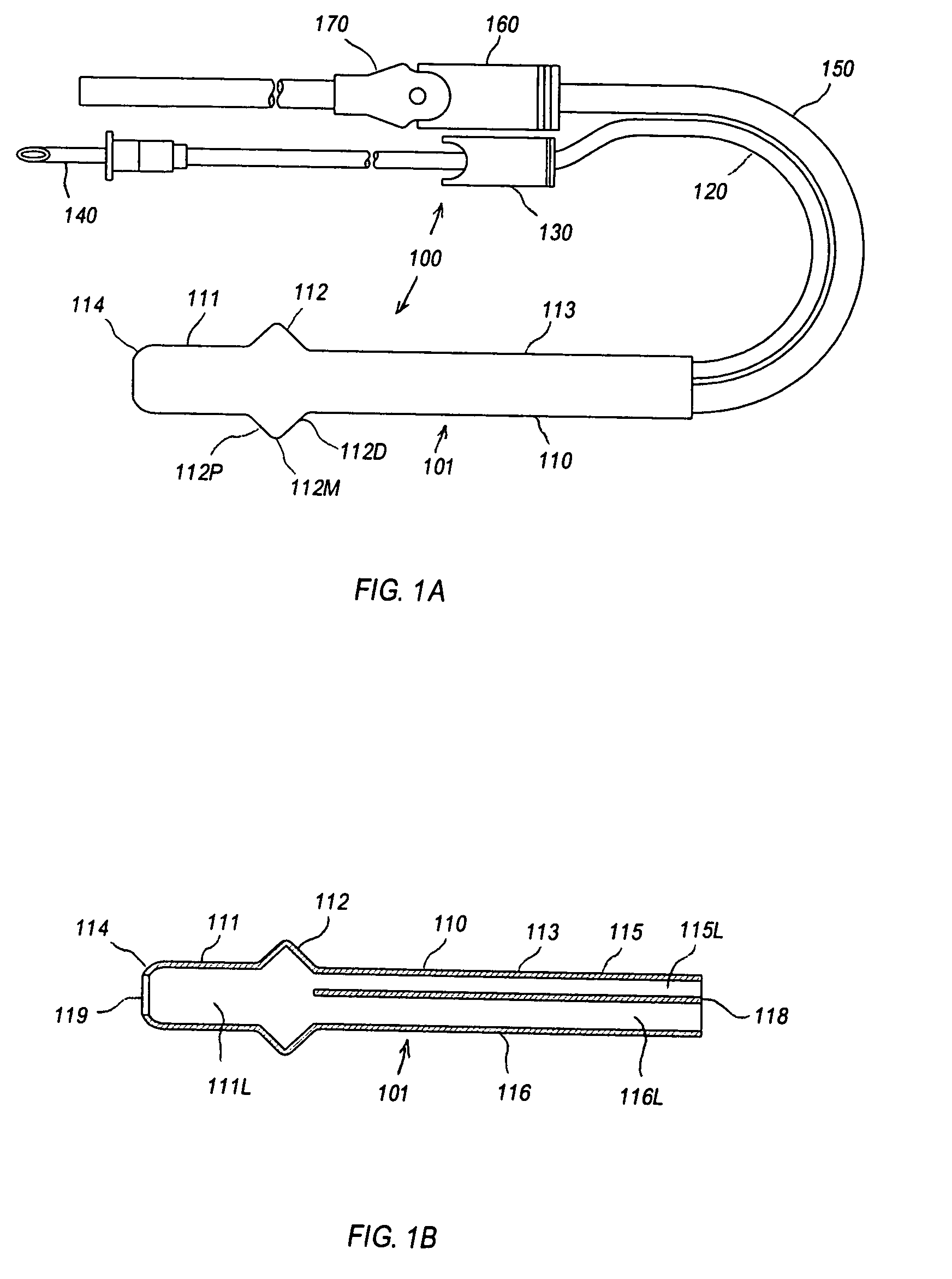
[0074] Referring to the accompanying drawings wherein like reference numerals refer to the same or similar elements, FIG. 1A shows this invention, a rectal irrigator for rectal lavage in accordance with the invention which is designated generally as 100. Rectal irrigator 100 comprises an irrigator device 101 having a substantially tubular body 110, inflow tubing 120, a clamp 130 to control fluid inflow via inflow tubing 120, a spike 140 coupled to an inlet end of inflow tubing 120 and which adapts to a fluid container (not shown), outflow tubing 150, a clamp 160 to control outflow via outflow tubing 150 and a suction control locator sleeve 170.

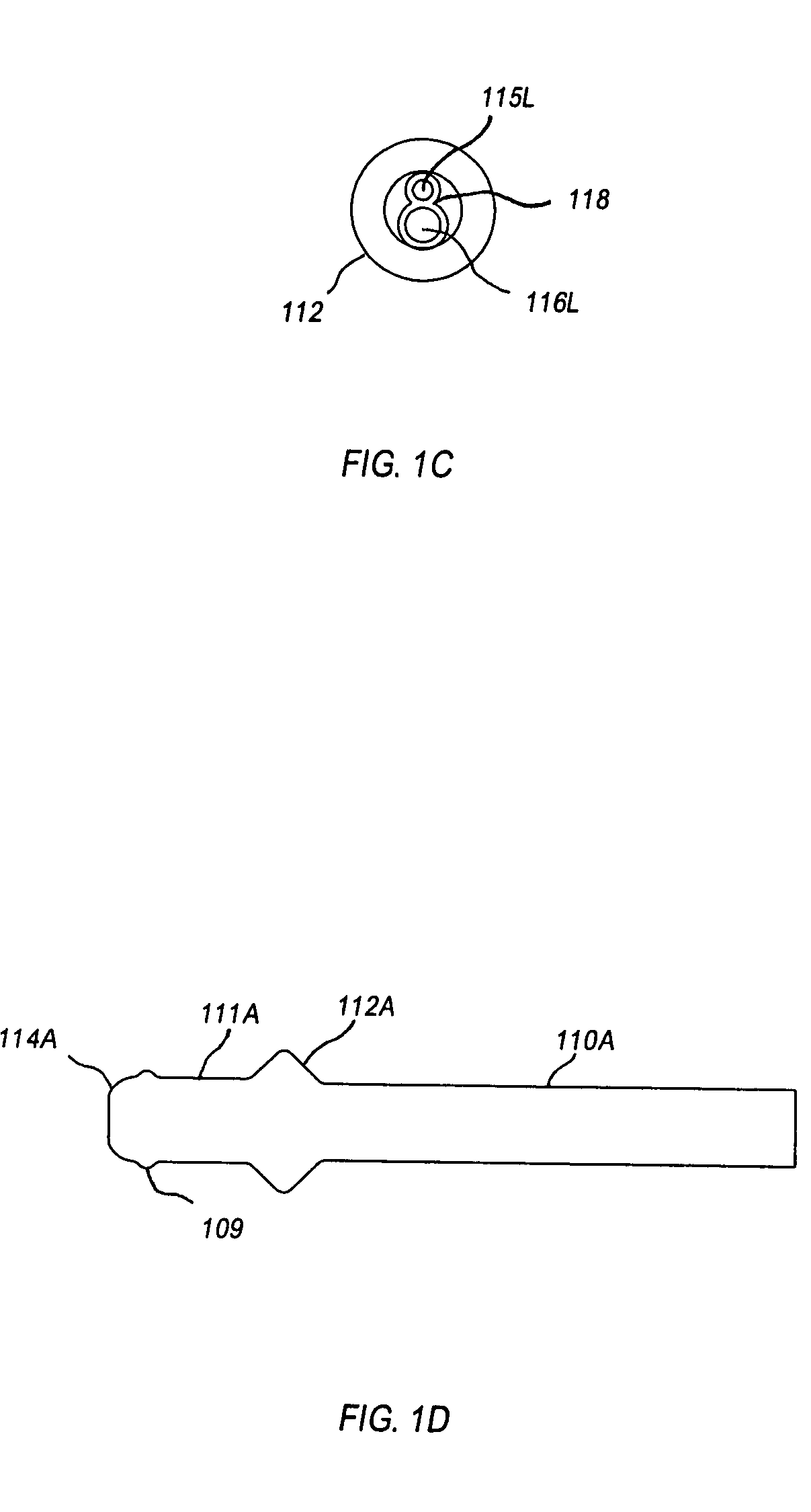
[0075] Tubular body 110 comprises a proximal segment or portion 111 and a distal segment or portion 113 separated from the proximal portion 111 by an expanded segment or portion 112. Tubular body 110 of the rectal irrigator 100 may be made of a plastic or elastomer compatible for contact with internal parts of the human body, namely the anal w...

second embodiment

[0090] Referring now to FIGS. 6A, 6B, 6C and 6D, the invention, a rectal irrigator for rectal lavage, is shown in its entirety in FIG. 6A and is designated generally as 200. Rectal irrigator 200 comprises essentially the same tubing and associated flow control devices as rectal irrigator 100, i.e., inflow tubing 120, clamp 130, spike 140, outflow tubing 150 and clamp 160, and a different irrigator device 201.

[0091] Irrigator device 201 includes a substantially tubular body 210 and a check valve 280 arranged in connection with tubular body 210.

[0092] Tubular body 210 comprises a proximal segment or portion 211 and a distal segment or portion 213 separated from the proximal portion 211 by an expanded segment or portion 212. Tubular body 210 of irrigator device 201 may be made of a plastic or elastomer compatible for contact with internal parts of the human body, namely the anal wall and anal opening as discussed below, and fabricated using a dip molding technique to obtain a soft, pl...

third embodiment

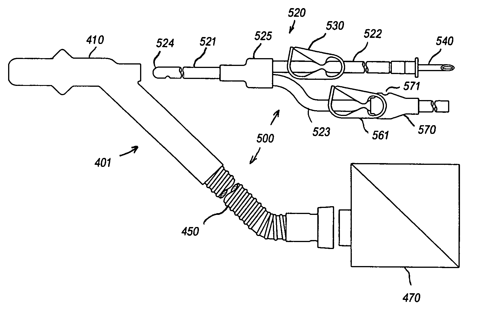
[0103] Referring now to FIGS. 8A, 8B, 8C and 8D, the invention, referred to as a rectocolonic irrigator, is useful when the patient is supine on the operating room table and when bowel to be lavaged includes a segment of sigmoid colon in addition to the rectum, and is shown in its entirety in FIG. 8A and designated generally as 300. Rectocolonic irrigator 300 comprises a drain assembly 301 having an angled tubular body 310, check valve 380 and outflow tubing 350, and colonic tube assembly 320.

[0104] Tubular body 310 comprises proximal portion 311 and distal portion 313 separated from the proximal portion 311 by expanded portion 312. Tubular body 310 may be made of a plastic or elastomer compatible for contact with internal parts of the human body, namely the anal wall and anal opening, and fabricated using a dip molding technique to obtain a soft, pliable form. Other materials and manufacturing methods can also be used.

[0105] Proximal portion 311 and expanded portion 312 have forms...


PUM


Abstract

Colorectal lavage device including a drain assembly, and a colonic tube assembly including an inflow tube, a flow control mechanism to control flow through the inflow tube, an outflow tube and a flow control mechanism to control flow through the outflow tube. The drain assembly has a tubular body defining an interior space and having a proximal portion insertable into an anus of a person to cause the anus to constrict around the proximal portion and thereby seal the proximal portion against the anal wall, a distal portion including a distal end having an opening in line with an opening in the proximal portion and a side tube arranged at an angle to the proximal portion. The inflow tube passes through the tubular body and has a tip with one or more apertures through which the lavage fluid operatively flows. The outflow tube is connected to the side tube.

Description

CROSS REFERENCE TO RELATED APPLICATIONS [0001] This application claims priority under 35 U.S.C. 119(e) of U.S. provisional patent application Ser. No. 60 / 592,888 filed Jul. 30, 2004 and U.S. provisional patent application Ser. No. 60 / 662,402 filed Mar. 16, 2005, the specification of each of which is incorporated by reference herein.FIELD OF THE INVENTION [0002] The present invention relates to devices for transanal lavage of the rectum and colon during a surgical operation. [0003] The present invention also relates to irrigator devices for use in, for example, irrigating the rectum, to suction control devices for use in connection with suction tubes to control the flow of suction therethrough and to colonic tubes and assemblies including the same for use in irrigating the colon. BACKGROUND OF THE INVENTION [0004] Surgical operations to remove the distal colon and part of the rectum are common for illnesses such as neoplasia, diverticular disease and inflammatory bowel disease. When ...

Claims


Application Information

Patent Timeline
Patent Type & Authority Applications(United States)
IPC IPC(8): A61M1/00
CPCA61M3/0283A61M2210/1067A61M3/0287A61M3/0208A61M3/0212A61M3/022A61M1/77
Inventor LEIBOFF, ARNOLD R.ZIPPER, JOSEPH
Owner LEIBOFF ARNOLD R
Why Eureka
Try Eureka