Top loading spinal fixation device and instruments for loading and handling the same

a spinal fixation device and top loading technology, applied in the field of spinal fixation devices, can solve the problems of limiting the angle of approach of the rod installing instrument which engages the head on both sides of the u-shaped channel with respect to the fastener, unable to enable the surgeon to maintain one hand, and limiting the access to the open channel

Inactive Publication Date: 2006-02-02
SYNTHES USA
View PDF99 Cites 337 Cited by
  • Summary
  • Abstract
  • Description
  • Claims
  • Application Information

AI Technical Summary

Benefits of technology

[0021] In another embodiment of an instrument for introducing an elongated spinal rod into a U-shaped channel of a bone fastener having a top opening, the instrument comprises a first member including a shaft, at least a portion of which has threads, the shaft having a longitudinal axis, a distal end configured for guiding the rod, a proximal end, and a knob associated with the proximal end. Alternatively, at least a portion of the first member may include external gear teeth. The first member and knob may also form a continuous through bore or channel extending from the proximal end to the distal end for receiving therein additional surgical instruments, for example a tool to secure a locking cap to secure the rod into the U-shaped channel. The rod introduction instrument further comprises a sleeve defining a longitudinal axis and having a through bore, the first member received in the through bore. In addition, the instrument comprises a second member having a first end and a second end, wherein the first end is configured to engage one of the side walls to secure the instrument to the fastener such that the instrument is disposed outside the passageway of the spinal rod defined by the U-shaped channel, preferably in

Problems solved by technology

A problem with an installation procedure requiring two tools is that does not enable the surgeon to maintain one hand free, possibly requiring multiple surgeons to complete the procedure.
Generally the instrument attaches in a manner that encroaches over the top opening of the U-shaped channel, severely limiting access to the open channel.
In addition, a rod installing instrument which engages the head on both sides of the U-shaped channel is limited in its angle of approach with respect to the fastener.
The surgical area may be reduced by the natural anatomy of the patient and an instrument that must be secured to both la

Method used


Image

  • Top loading spinal fixation device and instruments for loading and handling the same
  • Top loading spinal fixation device and instruments for loading and handling the same
  • Top loading spinal fixation device and instruments for loading and handling the same

Examples


Embodiment Construction

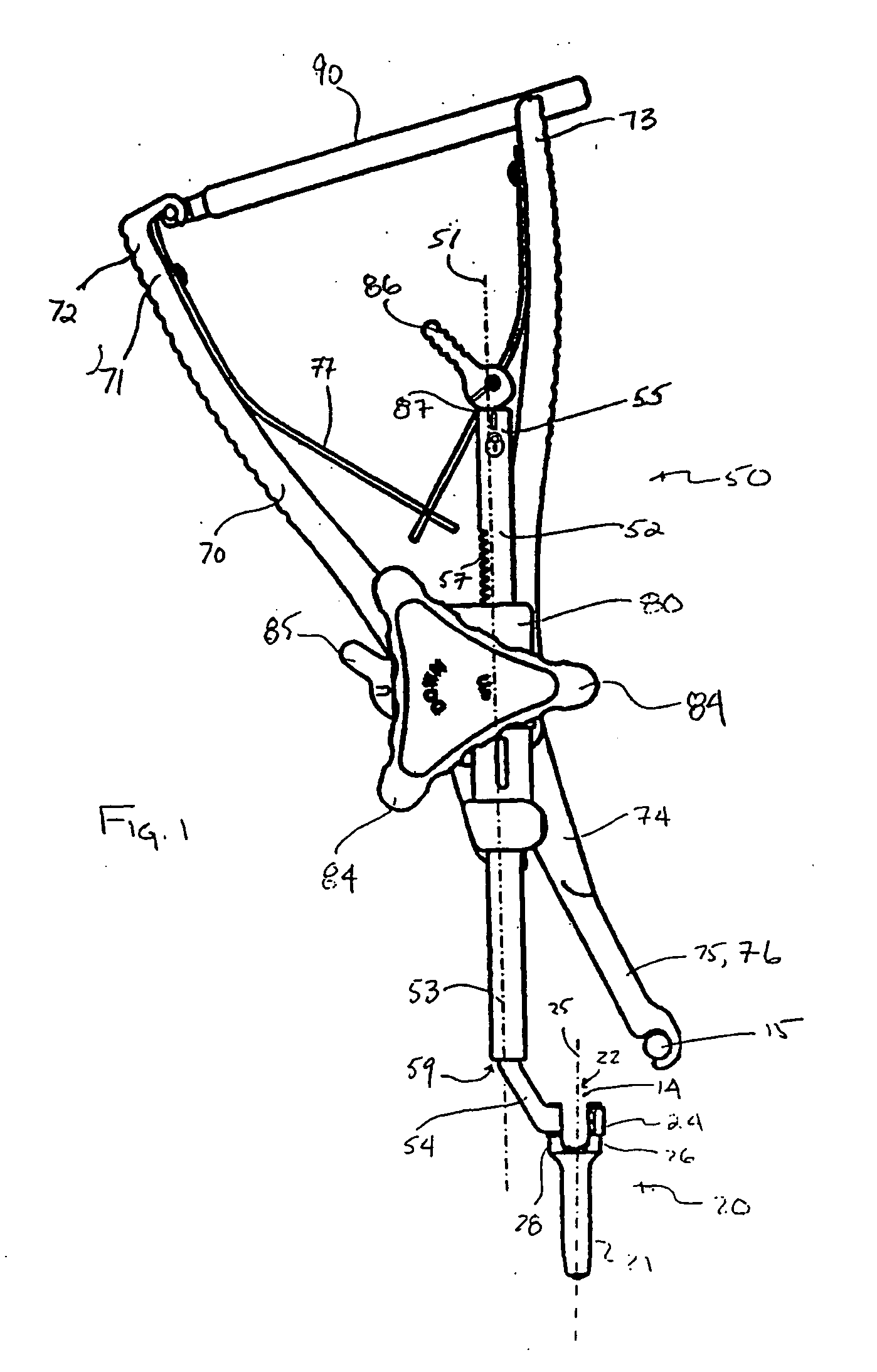
[0071] Referring to FIG. 1-12c there is shown a system for correction of spinal deformities including a bone fastener configured to fasten to the spine and having a U-shaped channel for receiving a longitudinal spinal rod. Several instruments are included in the system for handling and manipulating the bone fastener, as well as to manipulate and move the longitudinal spinal rod into the channel.

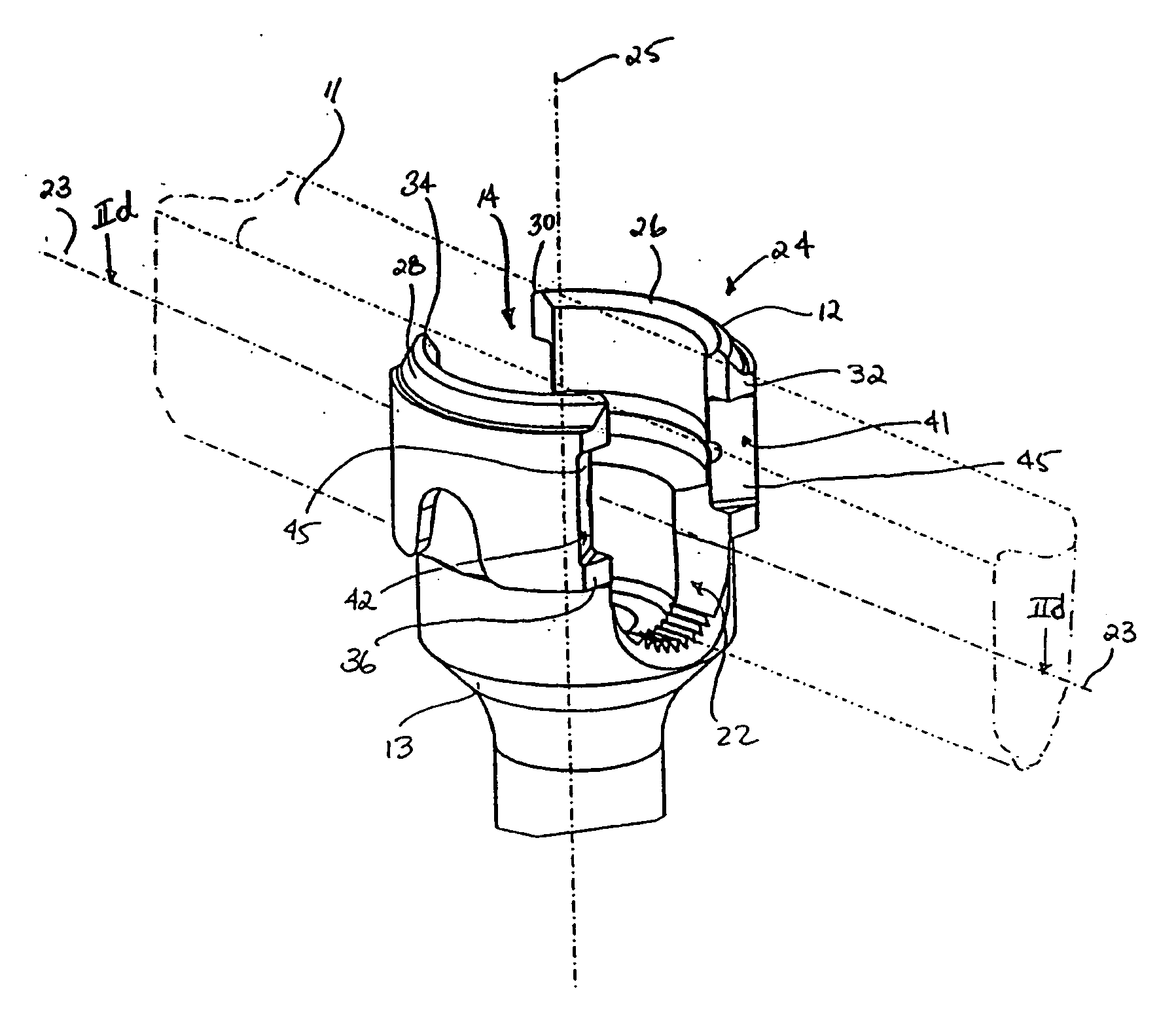
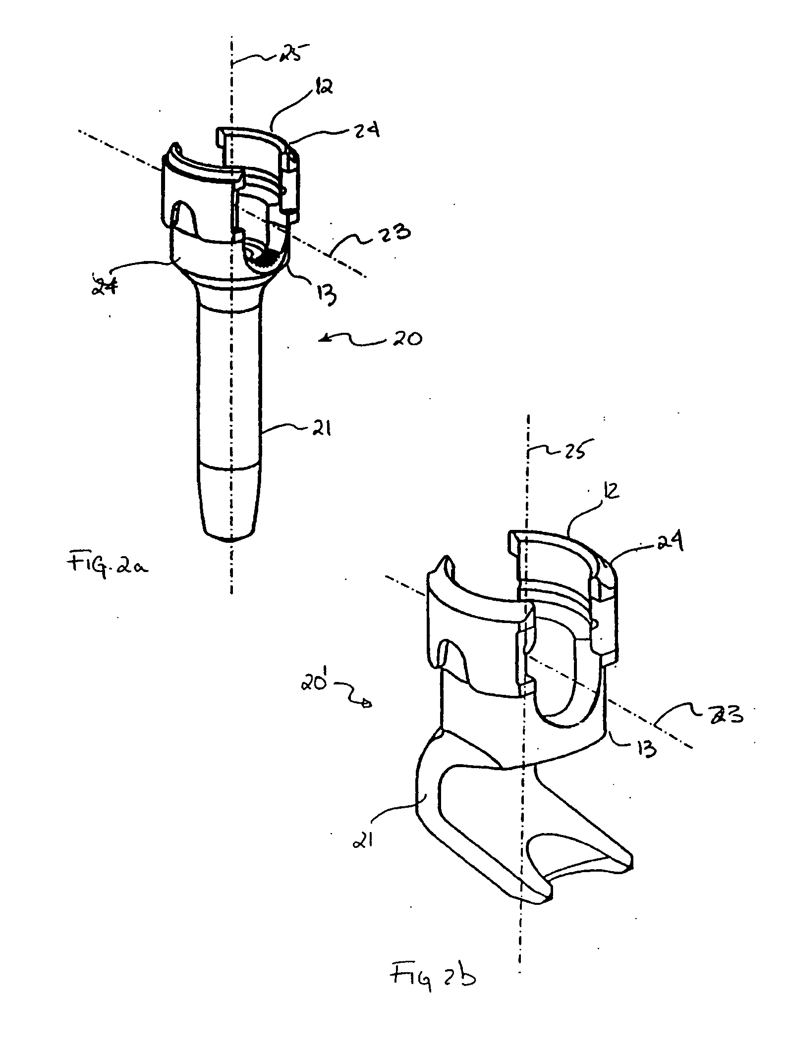
[0072]FIGS. 2a, 2b are first and second illustrative embodiments of bone fasteners 20, 20′ each having an enlarged head or body 24 and a bone engaging element 21, which defines a central axis 25. Shown in FIG. 2c is an enlarged view of the head 24, which includes a top surface 12, a bottom surface 13 and two lateral side walls 26, 28 defining a U-shaped channel 22 and a top opening 14 in the U-shaped channel 22. In the cross-section view of FIG. 2c, U-shaped channel 22 defines a longitudinal axis 23 normal to central axis 25. As will be discussed in greater detail below, U-shaped channel 22 ...


PUM


Abstract

A system for introducing an elongated spinal rod comprising a bone fastener having a head, the head including a top end, a bottom end, and a pair of side walls connected at the bottom end defining an elongated U-shaped channel having a first longitudinal axis and a top opening located at the top end. The top opening and the channel further define a passageway configured for receiving the spinal rod and each side wall further defining a first end face and a second end face, the second end face opposite the first end face. A bone engaging element extends from the bottom end of the head for anchoring the bone fastener to the bone. The system further comprises a tool for introducing the rod into the U-shaped channel. The tool includes a first member having a distal end and a proximal end. The distal end is configured for guiding the rod through the passageway to introduce the rod into the U-shaped channel through the top opening. A second member defines a second longitudinal axis substantially perpendicular to the first longitudinal axis. The second member has first and second ends, the second end having a pair of jaws for securing the tool to one of the side walls of the head of the bone fastener such that second member is disposed outside of the passageway of the spinal rod, and preferably so as not to interfere with or block access to the top opening. The first member is operably associated with the second member such that the first member is pivotable with respect to the second member and linearly translatable in a direction parallel to the second longitudinal axis between the first and second ends of the second member along the second longitudinal axis for introducing the spinal rod through the top opening into the passageway.

Description

FIELD OF THE INVENTION [0001] The present invention is directed to spinal fixation devices, more specifically, to bone screws having a rod receiving channel and the instruments for introducing spinal rods into the channel. BACKGROUND OF THE INVENTION [0002] To correct spinal deformities caused by either injury or defects in the natural formation of the spine, a spinal fixation system is typically employed in an osteosynthesis surgical procedure. A typical spinal fixation system may incorporate a plurality of bone fasteners substantially aligned along the length of the spine each interconnected by a spinal rod. The spinal rod is received in the channels formed in the head or body of the bone fasteners. The bone fastener may anchor to the lamina or pedicle of the vertebral body by either a threaded shank or hook which extends from the head or body of the fastener. The hook-type bone fastener may, in addition, be anchored to the transverse process. Typically, with the bone fasteners ri...

Claims


Application Information

Patent Timeline
IPC IPC(8): A61F2/30A61BA61B17/70A61B17/88
CPCA61B17/7004A61B17/7032A61B17/7088A61B17/7086A61B17/7076A61B17/70A61B17/72
Inventor IOTT, ANDYBINDER, LARRYDEC, BRIANBAKER, KELLY
Owner SYNTHES USA
Why Eureka
Try Eureka