
Surgical instrument incorporating an electrically actuated articulation mechanism

a surgical instrument and articulation mechanism technology, applied in the field of surgical instruments, can solve the problems of posing numerous challenges and barriers, complicated approaches to articulating surgical stapling and severing instruments,

Active Publication Date: 2006-02-02
CILAG GMBH INT
View PDF98 Cites 739 Cited by
  • Summary
  • Abstract
  • Description
  • Claims
  • Application Information

AI Technical Summary

Benefits of technology

The invention is a surgical instrument with a flexible shaft that can be controlled by an electroactive polymer (EAP) actuator. This allows for remote control of the instrument's movement, even if it has a small diameter. The technical effect is improved functionality and control of the surgical instrument.

Problems solved by technology

The technical problem addressed in this patent text is the need for an articulating surgical instrument that incorporates an articulation mechanism that requires less mechanical mechanisms passing through the shaft of the instrument. This articulation mechanism should allow for precise placement of the end effector at a desired surgical site and facilitate the use of additional functions such as buttress deployment and energy or fluid delivery without compromising the effectiveness of the instrument.

Method used


Image

  • Surgical instrument incorporating an electrically actuated articulation mechanism
  • Surgical instrument incorporating an electrically actuated articulation mechanism
  • Surgical instrument incorporating an electrically actuated articulation mechanism

Examples


Embodiment Construction

Surgical Instrument With EAP Actuated Flexneck Articulation Joint.

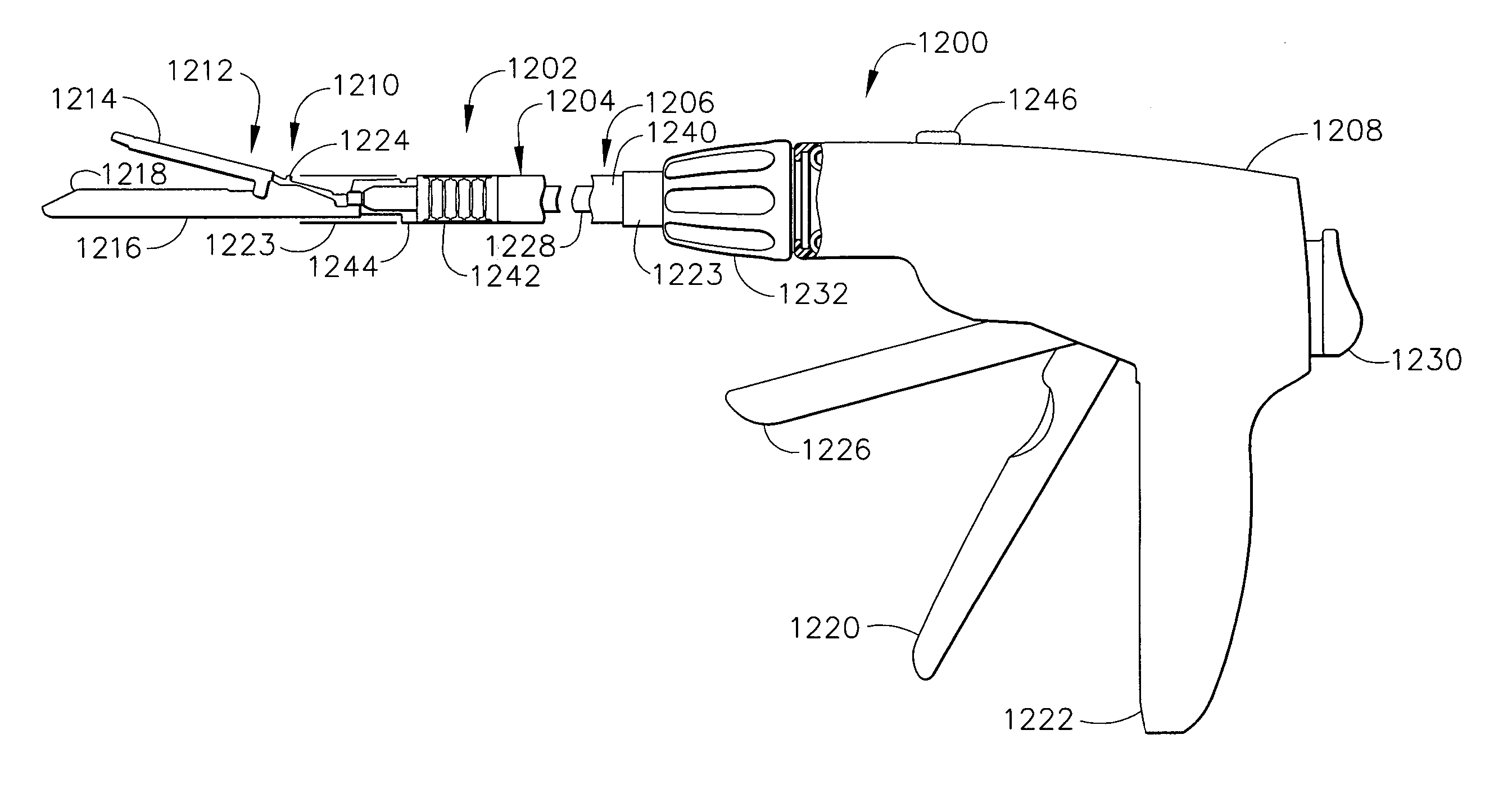
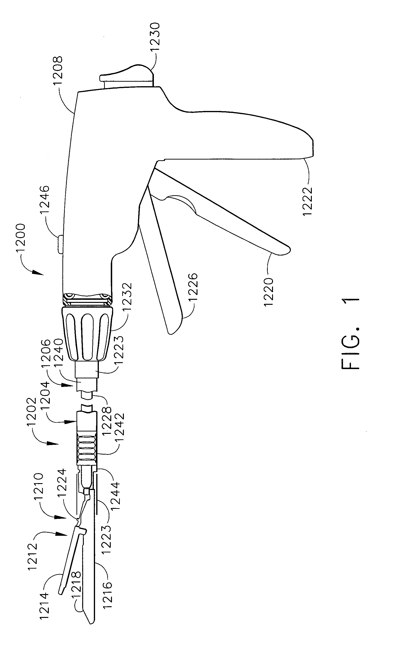
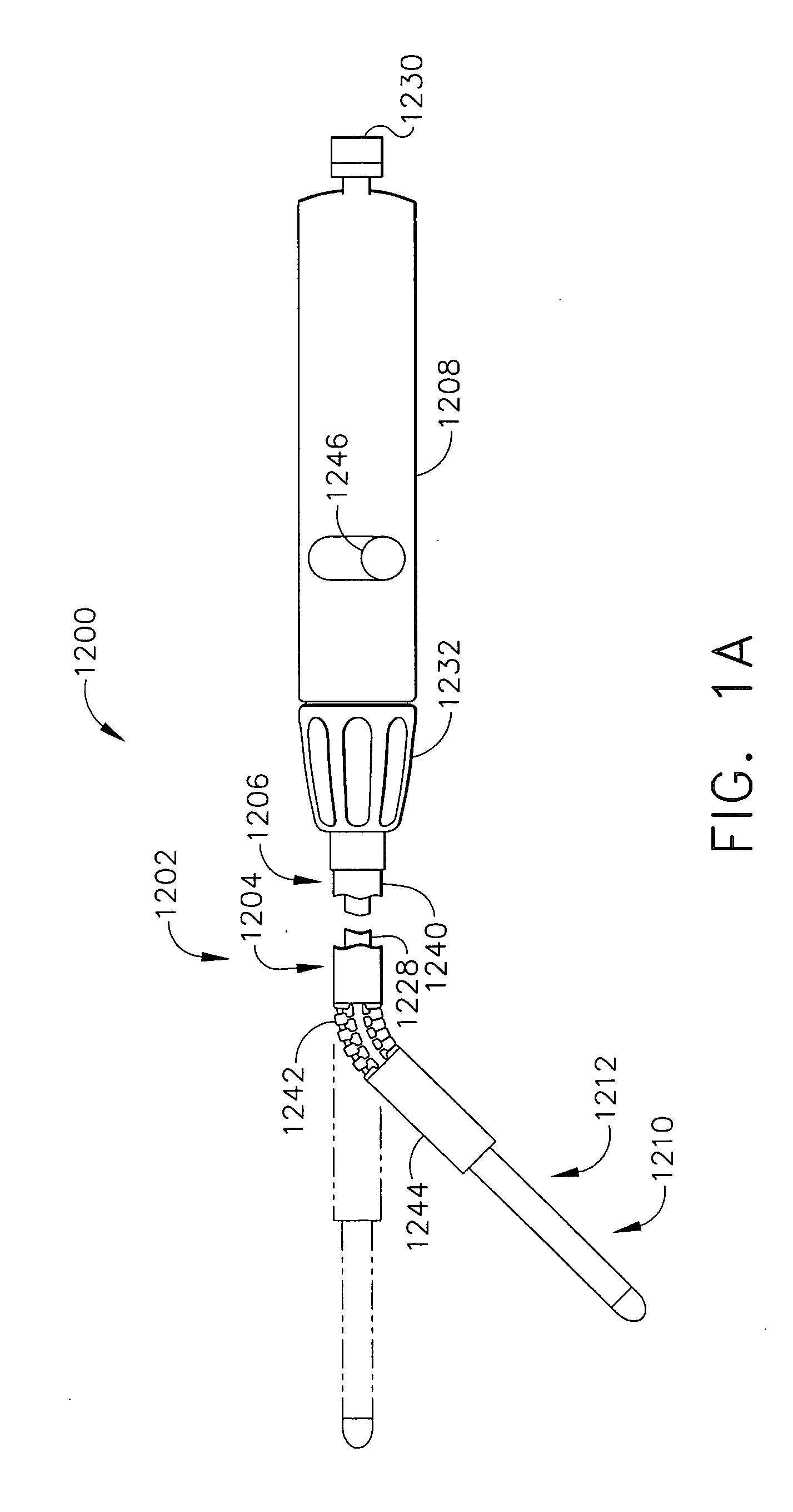
[0044] In FIG. 1, a surgical instrument 1200 advantageously incorporates an EAP actuated articulation joint 1202 that is integral to an articulating frame assembly 1204 of an elongate shaft 1206 that transfers separate closure and firing motions from a handle 1208 to an end effector 1210, depicted as a staple applying assembly 1212 having a closeable anvil 1214 that is pivotally attached to an elongate channel 1216 that holds a replaceable staple cartridge 1218. The handle 1208 includes a closure trigger 1220 that is squeezed proximally toward a pistol grip 1222 to effect closure of the anvil 1214. It should be appreciated that a closure sleeve assembly 1223 or other closure means (e.g., EAP actuated anvil, internal longitudinally translating member, etc.) that is not shown acts upon an anvil closure feature 1224 to effect opening and closing of the anvil 1214. Once closed and clamped, a more distal firing trigger 1...


PUM

PropertyMeasurementUnit
Lengthaaaaaaaaaa
Flexibilityaaaaaaaaaa
Responsivityaaaaaaaaaa

Abstract

A surgical instrument particularly suited to endoscopic use articulates an end effector by including an articulation mechanism in an elongate shaft that incorporates an electrically actuated polymer (EAP) actuator for remotely articulating the end effector. In particular, a flexible neck to a frame of the elongate neck may be laterally urged to the left or right by EAP actuators and advantageously locked into an articulated state.

Description


Claims


Application Information

Patent Timeline
Owner CILAG GMBH INT
Features
  • Generate Ideas
  • Intellectual Property
  • Life Sciences
  • Materials
  • Tech Scout
  • Unparalleled Data Quality
  • Higher Quality Content
  • 60% Fewer Hallucinations
Learn More