Thalamic stimulation device

a thalamus and electrode technology, applied in the direction of head electrodes, internal electrodes, therapy, etc., can solve the problems of not providing precise targeting of the thalamus, current electrical leads used in deep brain stimulation,

Inactive Publication Date: 2006-02-02
THE CLEVELAND CLINIC FOUND
View PDF11 Cites 103 Cited by
  • Summary
  • Abstract
  • Description
  • Claims
  • Application Information

AI Technical Summary

Problems solved by technology

Current electrical leads used in deep brain stimulation, however, do not provide precise targeting of the areas of the thalamus such as the intralaminar nuclei, such that the desired volume of tissue is stimulated.

Method used


Image

  • Thalamic stimulation device
  • Thalamic stimulation device
  • Thalamic stimulation device

Examples


Embodiment Construction

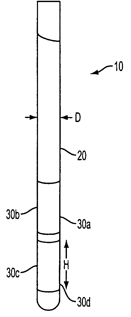
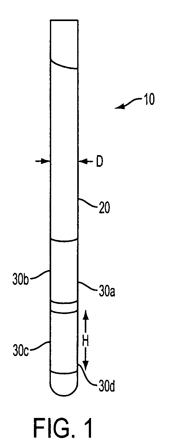
[0013] Referring to FIG. 1, in an embodiment, the present invention provides an electrical lead 10 comprising a body 20 having electrodes 30 thereon. Preferably, electrical lead 10 has any one of, all of, or any combination of the following features: body 20 has a diameter D of between about 0.75 to about 1.25 millimeters (mm); body 20 has about 4 to about 6 electrodes 30 thereon; electrodes 30 each span about 110 to about 170 degrees about body 20; and at least one of and preferably all of electrodes 30 have a height H of between about 3 to about 4 mm.

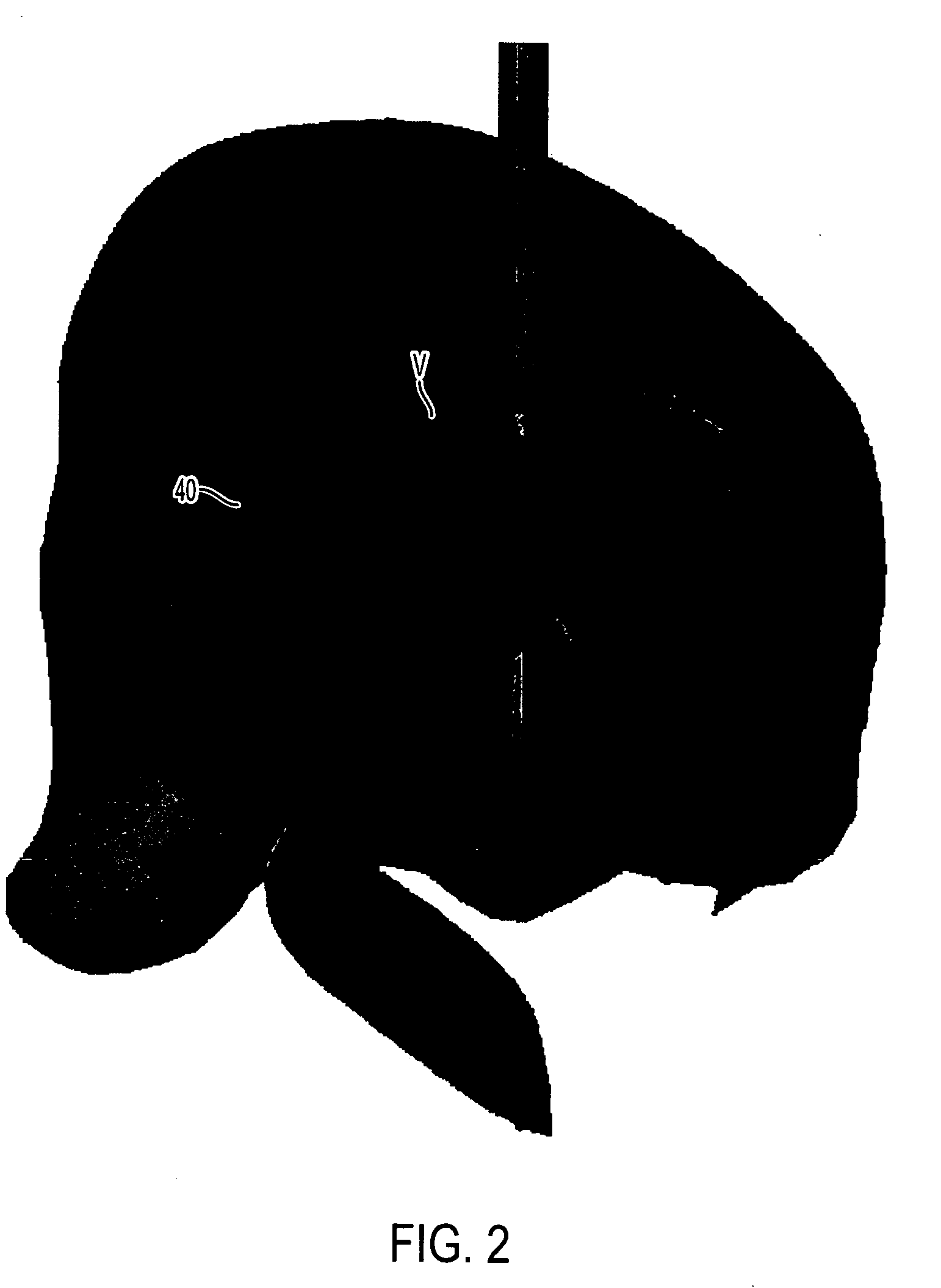
[0014] Electrical lead 10 can be used to stimulated specific regions of the thalamus to provide precise directional stimulation of such specific regions. For example, referring to FIG. 2, which is a schematic illustration of electrical stimulation of regions of the thalamus by electrical lead 10 positioned in the thalamus, activation of electrode 30b results in a volume of activation V that reaches the intralaminar nuclei as well as ...


PUM


Abstract

The present invention provides an electrical lead configured for stimulation of the thalamus. The electrical lead provides for preferential stimulation of the medial or lateral thalamus as well as specific nuclei within the thalamus, such as the intralaminar nuclei.

Description

CROSS-REFERENCE TO RELATED APPLICATIONS [0001] The present application claims priority to U.S. Provisional Application No. 60 / 591,210, filed on Jul. 27, 2004, which is incorporated by reference herein.FIELD OF THE INVENTION [0002] The present application is directed to an implantable electrical stimulation device configured to stimulate target sites of the thalamus. BACKGROUND OF THE INVENTION [0003] Deep brain stimulation is becoming an increasingly preferred form of therapy for certain neurological conditions and disorders. Such therapy provides distinct advantages over surgical lesioning techniques, which are still being used to affects disorders such as Parkinson's disease, essential tremor, and dystonia. In particular, unlike surgical lesioning techniques, electrical stimulation is a reversible and adjustable procedure that provides continuous benefits as the patient's disease progresses and the patient's symptoms evolves. Currently, deep brain stimulation of the subthalamic nu...

Claims


Application Information

Patent Timeline
Patent Type & Authority Applications(United States)
IPC IPC(8): A61N1/05
CPCA61N1/3605A61N1/0534
Inventor MCINTYRE, CAMERON
Owner THE CLEVELAND CLINIC FOUND
Why Eureka
Try Eureka