Modular implant assembly tool

a technology of modular implants and assembly tools, which is applied in the field of medical equipment and procedures, can solve problems such as bone fractures, premature implant failure, and premature failure of implants

Inactive Publication Date: 2006-02-09
SERRA MICHAEL A +1
View PDF22 Cites 29 Cited by
  • Summary
  • Abstract
  • Description
  • Claims
  • Application Information

AI Technical Summary

Problems solved by technology

Due to the frictional nature of these locking tapers, large assembly loads are generally needed to completely and securely join the components.
However, if the assembly loads are too large, detrimental stresses may be applied to the implant which may result in premature failure.
While these approaches can be effective, they are also inconsistent.
Factors such as hammer weight, the number of blows, and surgical technique can lead to assembly loads that are either too low (so that they result in ineffective locking) or too large (so that they impart undesirably large stresses in the parts), either of which may result in premature implant failure.
In addition, in some cases where the patient's bone quality is poor, aggressive impactions can lead to fractures of the bone and poor surgical outcomes.
Poor bone quality may also lead to under-assembled components because a large frictional interface is generally needed between the bone and the implant in order to produce enough resistance to fully assemble the components.
However, this approach generally lacks sufficient accuracy due to the change in mechanical advantage that occurs as the handles are brought together.
The device as disclosed in U.S. Pat. No. 6,238,435, has a significant disadvantage when compared to an object of the present invention, when considering the indication of force.
Because the force applied to the taper junction is a cosine function of the force applied to the handles, the surgeon is unable to detect or measure the force applied directly to the taper junction.
The device as disclosed in U.S. Pat. No. 6,238,435, has a significant further disadvantage when compared to an object of the present invention, when considering the surgeon's perspective of the force applied to the handles, the angle between the handles, and the force applied to drawing the tapers together.
However, once the taper junction is drawn together, using the device as disclosed in U.S. Pat. No. 6,238,435, the angle between the handles cannot be changed regardless of the force applied to the handles.
No existing design directly measures the true axial force generated.
No existing design permits the generation of a pre-determined axial force.

Method used


Image

  • Modular implant assembly tool
  • Modular implant assembly tool
  • Modular implant assembly tool

Examples


Embodiment Construction

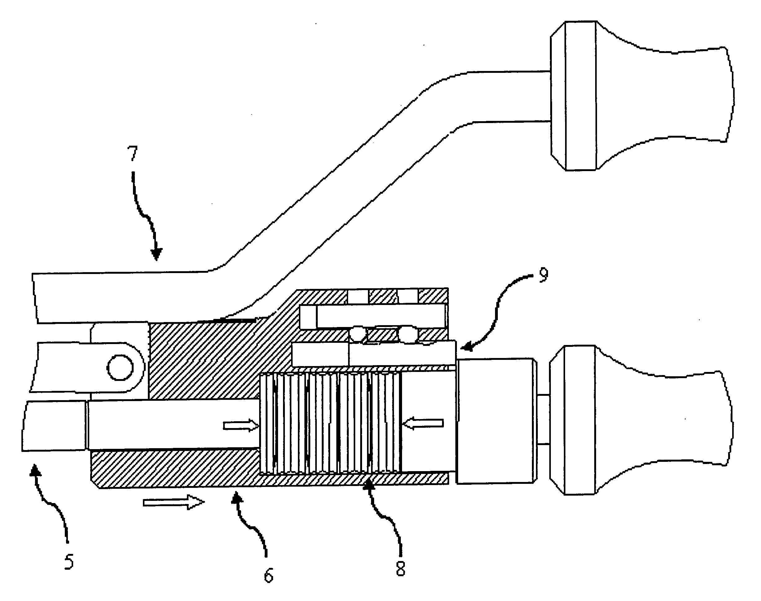
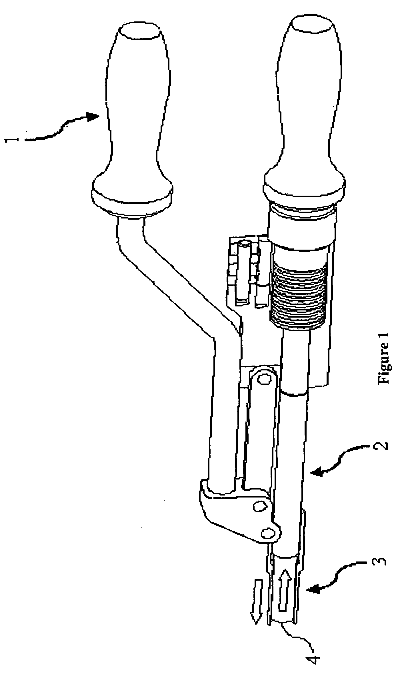
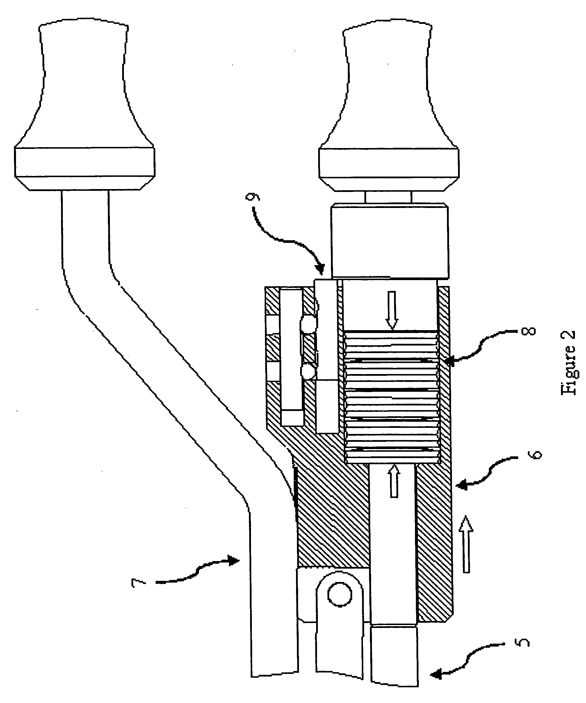
[0021] This invention improves upon existing designs by directly measuring, independently from input variables, the axial force generated while assembling modular implant components.

[0022] In a preferred embodiment of the present invention, this is accomplished by using a spring (or springs) to measure the true axial force being exerted. Springs deflect a predictable amount under load. If this deflection is measured and the spring rate is known, a force can be calculated.

[0023] In one embodiment this deflection can be measured using a scale. This scale may be labeled with force as the units. The scale may also represent a range of desirable loads. This range may be labeled with text, or color coded, to indicate adequate or inadequate assembly loads.

[0024] In another embodiment of the present invention, the required spring deflection may activate a trigger that alerts the user that the desired load has been reached. This trigger may release a button, make a sound, switch on a ligh...


PUM

PropertyMeasurementUnit
forceaaaaaaaaaa
displacementaaaaaaaaaa
piezoelectric voltageaaaaaaaaaa

Abstract

This invention provides for a tool that produces, and directly and accurately measures, an axial force used to assemble two members of a modular implant, specifically, a modular hip implant.

Description

REFERENCE TO PENDING PRIOR PATENT APPLICATION [0001] This patent application claims benefit of pending prior U.S. Provisional Patent Application Ser. No. 60 / 378,974, filed May 09, 2002 by Michael A. Serra et al. for DIRECT TENSION MEASURING IMPLANT ASSEMBLY TOOL (Attorney's Docket No. HAYES-10 PROV), which patent application is hereby incorporated herein by reference.FIELD OF THE INVENTION [0002] This invention relates to medical apparatus and procedures in general, and more particularly to medical apparatus and procedures relating to total hip joints. BACKGROUND OF THE INVENTION [0003] Modular orthopedic implants are implants that comprise multiple components that are assembled at the time of surgery. In the case of a modular hip prosthesis, there may be separate stem, body, and neck segments. These orthopedic devices often use a self-locking taper to join the multiple components of the implant together. These tapers provide a strong frictional joint that resists the torsional load...

Claims


Application Information

Patent Timeline
Patent Type & Authority Applications(United States)
IPC IPC(8): G01N3/08A61F2/00A61F2/36A61F2/46
CPCA61F2/3609A61F2/4637A61F2/4657A61F2002/30332A61F2002/30604A61F2002/4622A61F2220/0033A61F2002/4666A61F2002/4689A61F2002/469A61F2002/4696A61F2002/4697A61F2002/4623A61F2/4603
Inventor SERRA, MICHAEL A.DESPRES, ALFRED S.
Owner SERRA MICHAEL A
Why Eureka
Try Eureka