Steering column device

Inactive Publication Date: 2006-02-09
NSK LTD
View PDF15 Cites 104 Cited by
  • Summary
  • Abstract
  • Description
  • Claims
  • Application Information

AI Technical Summary

Benefits of technology

[0012] It is an object of the present invention to provide a steering column device in which an outer column and an inner column are axially and slidably fitted to each other, a structure of the distance b

Problems solved by technology

However, the prior art constitution in which the distance bracket is welded to the outer column or integrally formed by a

Method used


Image

  • Steering column device
  • Steering column device
  • Steering column device

Examples


Embodiment Construction

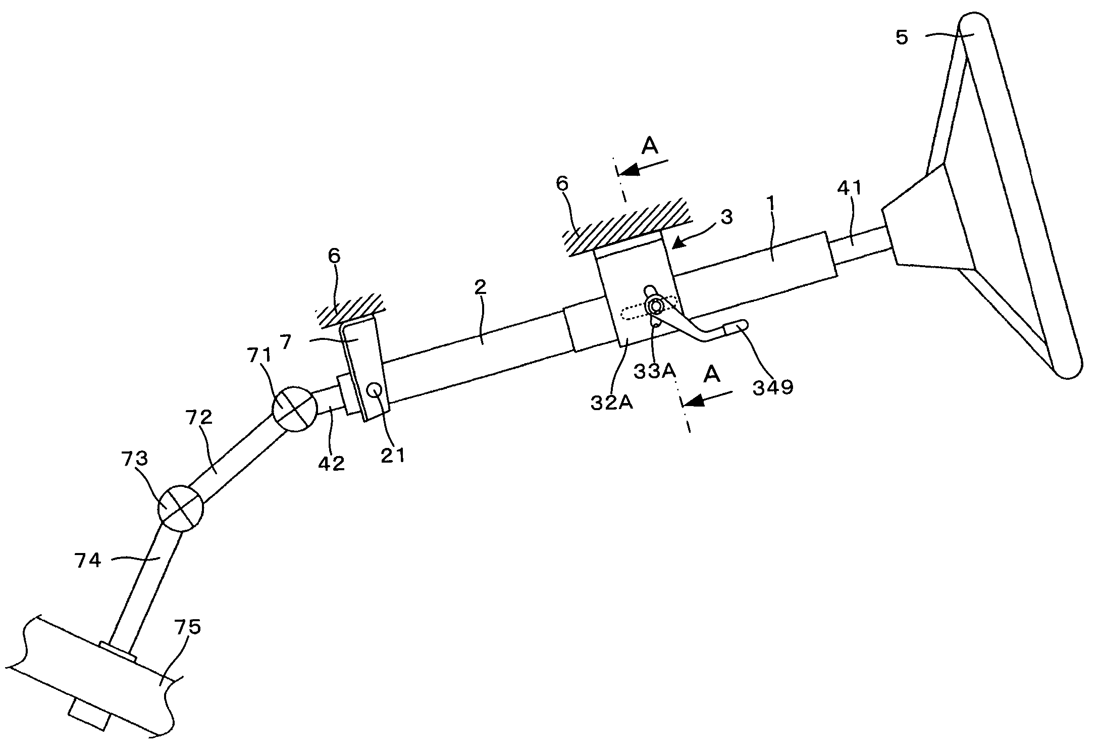
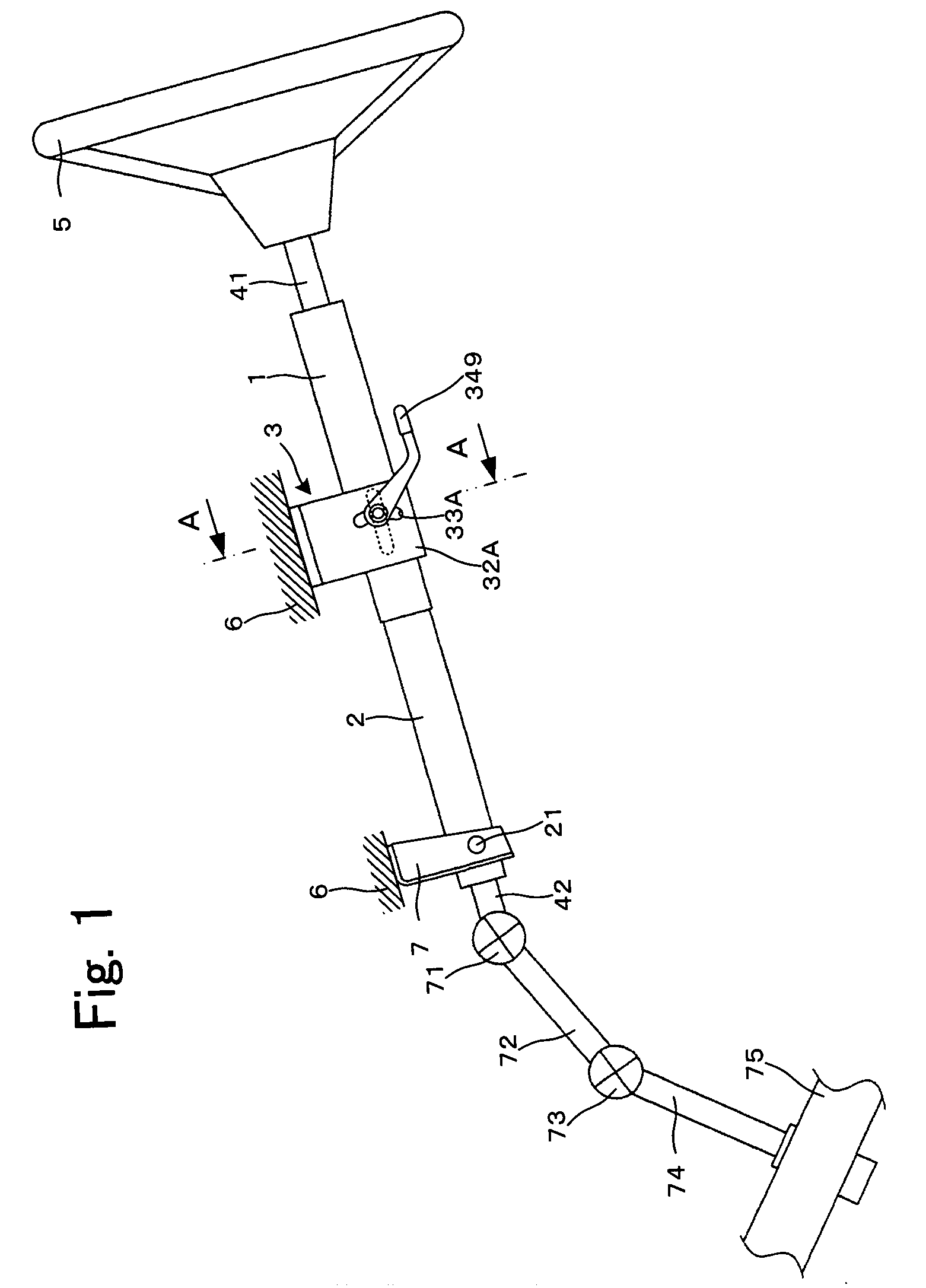
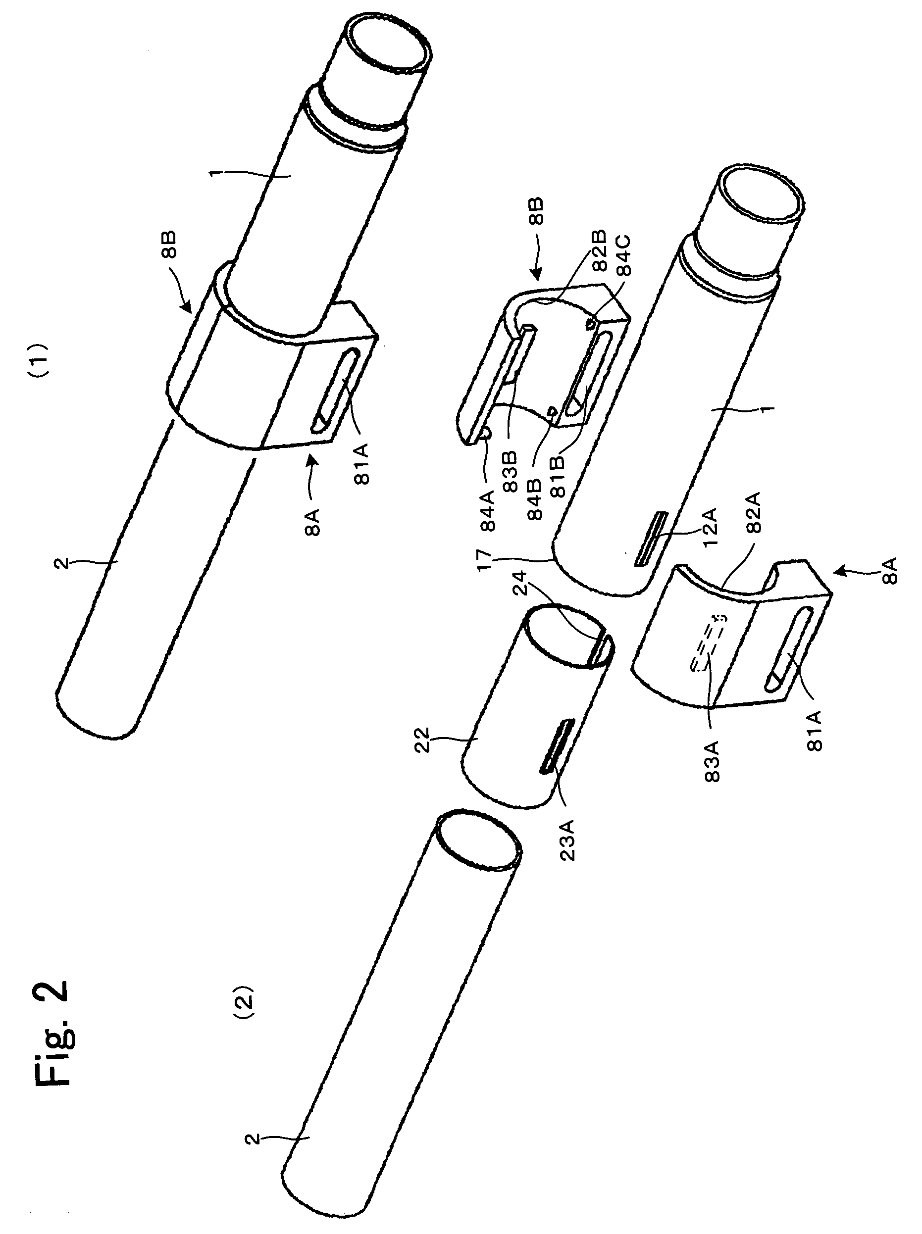
[0049] Referring now to the drawings, some preferred embodiments of the present invention will be described as follows. FIG. 1 is an entire view for showing a steering column device of the present invention. FIG. 2 shows a substantial part of the steering column device in accordance with a first preferred embodiment of the present invention, wherein (1) is a perspective view for showing an assembled state and (2) is a decomposed perspective view. FIG. 3 is a longitudinal section of the steering column device in accordance with a first preferred embodiment of the present invention and this sectional view corresponds to a sectional view taken along line A-A of FIG. 1.

[0050] As shown in FIG. 1, an upper steering shaft 41 having a steering wheel 5 fixed to a rear side of the vehicle body (the right side in FIG. 1) is rotatably supported in a hollow cylindrical outer column 1. An inner column 2 is axially and slidably fitted to a front side of the vehicle body (the left side in FIG. 1) ...


PUM


Abstract

A structure of the steering column device for clamping the outer column to the inner column is simple and its manufacturing cost is reduced. The outer column 1 and the bushing are stopped against rotation to the clamp members and at the same time when the outer column is adjusted in its telescopic position in respect to the inner column, the outer column, clamp members and bushing can be integrally and axially slid. Since the bushing having a low frictional coefficient is present between the inner circumference of the outer column and the outer circumference of the inner column, the outer column can be moved with a light force in respect to the inner column.

Description

FIELD OF THE INVENTION [0001] The present invention relates to a steering column device and more particularly to a steering column device in which an outer column and an inner column are axially and slidably fitted to each other to cause a telescopic position of a steering wheel to be adjusted or when a secondary collision occurs, the steering wheel is collapsed and moved to absorb collision load. BACKGROUND OF THE INVENTION [0002] There is provided a steering column device in which the outer column and the inner column are axially and slidably fitted to each other to cause a telescopic position of the steering wheel to be adjusted or a collision load at the time of secondary collision. In such a steering column device described above, a distance bracket for use in clamping the inner column while the diameter of the outer column is reduced is integrally formed with the outer column. [0003] For example, when the outer column is formed by a steel pipe, the distance bracket formed by a...

Claims


Application Information

Patent Timeline
IPC IPC(8): B62D1/18
CPCB62D1/184B62D1/192B62D1/185
Inventor YAMADA, JUN
Owner NSK LTD
Why Eureka
Try Eureka