Direct current offset cancellation and phase equalization for power metering devices

a technology of direct current offset and power metering device, which is applied in the direction of power measurement by digital technique, dynamo-electric motor meters, instruments, etc., can solve the problems of reducing the criticality of phase response, limiting the operating frequency bandwidth, and relaxing the design complexity of high-pass filters. , to achieve the effect of reducing the criticality of phase response, limiting the operating frequency bandwidth, and reducing the accuracy of measuremen

Inactive Publication Date: 2006-02-09
MICROCHIP TECH INC
View PDF30 Cites 21 Cited by
  • Summary
  • Abstract
  • Description
  • Claims
  • Application Information

AI Technical Summary

Benefits of technology

[0006] A technical advantage of the present invention is that phase matching between the two channels is inherent because the high-pass filters of the same design may be used for each of the two channels (voltage and current). This results in maintaining substantially zero phase difference throughout the entire frequency range of operation, thus limiting operating frequency bandwidth to ensure the accuracy of the measurement is no longer required. Also, reducing the criticality of phase response over frequency relaxes design complexity of the high-pass filter.
[0007] According to a specific exemplary embodiment of the invention, using two high-pass filters with matched phase responses, one high-pass filter (HPF) for each of the two channels (voltage and current), reduces the design constraints since each channel may have different gains and the prior art requirement of using an additional phase compensation block is no longer needed. Thus, relaxed requirements for the channel high-pass filters reduces the required design time. Additional benefits are the gain error term at the output of the multiplier is now a function of only one variable (the gain of the HPF) which relaxes the design constraints on the HPF. The gain error term is now the square of the HPF gain for the measured frequency which defines the constraints on the HPF design. Moreover, there is no more ω component in the output product which makes the low-pass filter (“LPF”) easier to design since only the 2ω component need be reject.
[0008] Other technical advantages should be apparent to one of ordinary skill in the art in view of what has been disclosed herein.

Problems solved by technology

This results in maintaining substantially zero phase difference throughout the entire frequency range of operation, thus limiting operating frequency bandwidth to ensure the accuracy of the measurement is no longer required.
Also, reducing the criticality of phase response over frequency relaxes design complexity of the high-pass filter.

Method used


Image

  • Direct current offset cancellation and phase equalization for power metering devices
  • Direct current offset cancellation and phase equalization for power metering devices
  • Direct current offset cancellation and phase equalization for power metering devices

Examples


Embodiment Construction

[0013] Referring now to the drawings, the details of a specific exemplary embodiment of the present invention is schematically illustrated. Like elements in the drawings will be represented by like numbers, and similar elements will be represented by like numbers with a different lower case letter suffix.

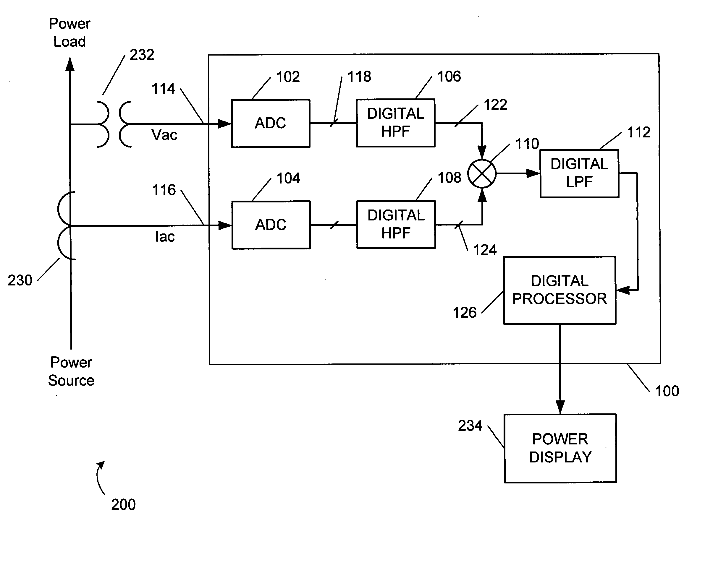
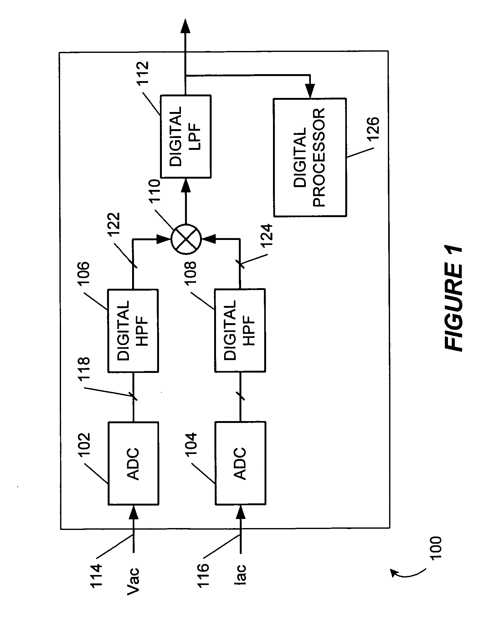
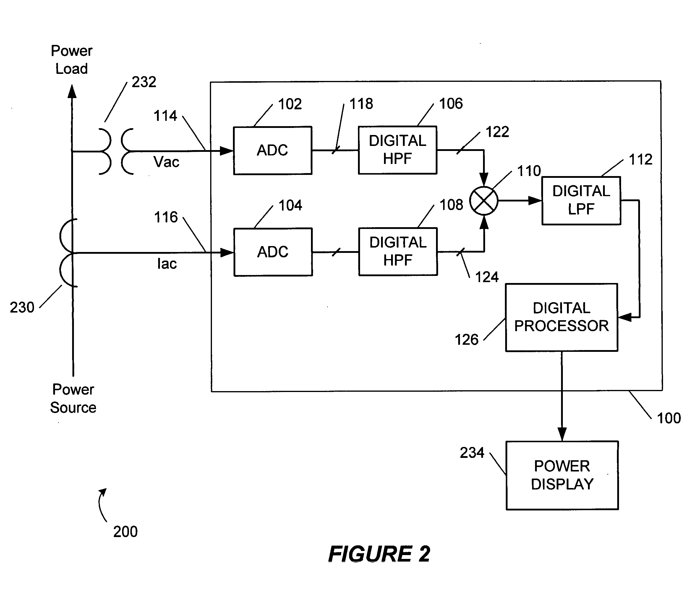
[0014] Referring to FIG. 1, depicted is a schematic block diagram of a power metering device, according to a specific exemplary embodiment of the invention. The power metering device, generally represented by the numeral 100, comprises a first analog-to-digital convert (ADC) 102, a second ADC 104, a first digital high pass filter (HPF) 106, a second digital HPF 108, a multiplier 110, and a digital low pass filter (LPF) 112. For power metering, direct current (DC) offset must be substantially reduced (canceled). The first and second ADCs 102 and 104 are preferably Sigma Delta ADCs, and preferably have substantially the same output data rates. However, a difference in output data rat...


PUM


Abstract

A power metering device having direct current offset cancellation and phase equalization between the voltage and current channels by using two high-pass filters, one for each channel, and further removing the ω(2πf) component of the power term for less critical low-pass filter design.

Description

RELATED PATENT APPLICATION [0001] This application claims priority to commonly owned U.S. Provisional Patent Application Ser. No. 60 / 599,282; filed Aug. 5, 2004; entitled “Direct Current Offset Cancellation And Phase Equalization For Power Metering Devices,” by Vincent Quiquempoix, which is hereby incorporated by reference herein for all purposes.TECHNICAL FIELD OF THE INVENTION [0002] The present invention relates to electronic power metering, more particularly, to direct current offset cancellation and phase equalization in a power metering device. BACKGROUND OF THE RELATED TECHNOLOGY [0003] In power metering or measurement systems, measured analog current and voltage channels are often digitized for ease in performing digital signal processing on the voltage and current information so as to produce a more accurate power measurement than could be obtained from a completely analog power metering system. However, the analog electronics of the power metering system and the analog-to-...

Claims


Application Information

Patent Timeline
Patent Type & Authority Applications(United States)
IPC IPC(8): G01R11/32
CPCG01R21/133G01R19/2513
Inventor QUIQUEMPOIX, VINCENT
Owner MICROCHIP TECH INC
Why Eureka
Try Eureka