Method for recognising obstacles and for predicting the change of position of known obstacles by means of signals from a plurality of sensors and for compressing and decompressing sensor signals used for the above purposes

A sensor signal and sensor technology, applied to identify obstacle objects based on signals from multiple sensors and predict changes in the position of known obstacle objects, and to compress and process sensor signals used for the above purposes In the field of decompression, it can solve problems that do not involve object recognition, object recognition of undescribed obstacles, etc.

Pending Publication Date: 2021-12-21
ELMOS SEMICON SE
View PDF19 Cites 1 Cited by
  • Summary
  • Abstract
  • Description
  • Claims
  • Application Information

AI Technical Summary

Problems solved by technology

However, this known method does not involve the implementation of object recognition
[0018] Methods for transmitting data from an ultrasound system to a data processing device via a vehicle bus are known from DE-B-10 2018 106 244 and DE-A-10 2019 106 190 (published only after the priority date of this PCT application) , but does not describe how to perform obstacle object recognition

Method used


Image

  • Method for recognising obstacles and for predicting the change of position of known obstacles by means of signals from a plurality of sensors and for compressing and decompressing sensor signals used for the above purposes
  • Method for recognising obstacles and for predicting the change of position of known obstacles by means of signals from a plurality of sensors and for compressing and decompressing sensor signals used for the above purposes
  • Method for recognising obstacles and for predicting the change of position of known obstacles by means of signals from a plurality of sensors and for compressing and decompressing sensor signals used for the above purposes

Examples


Embodiment Construction

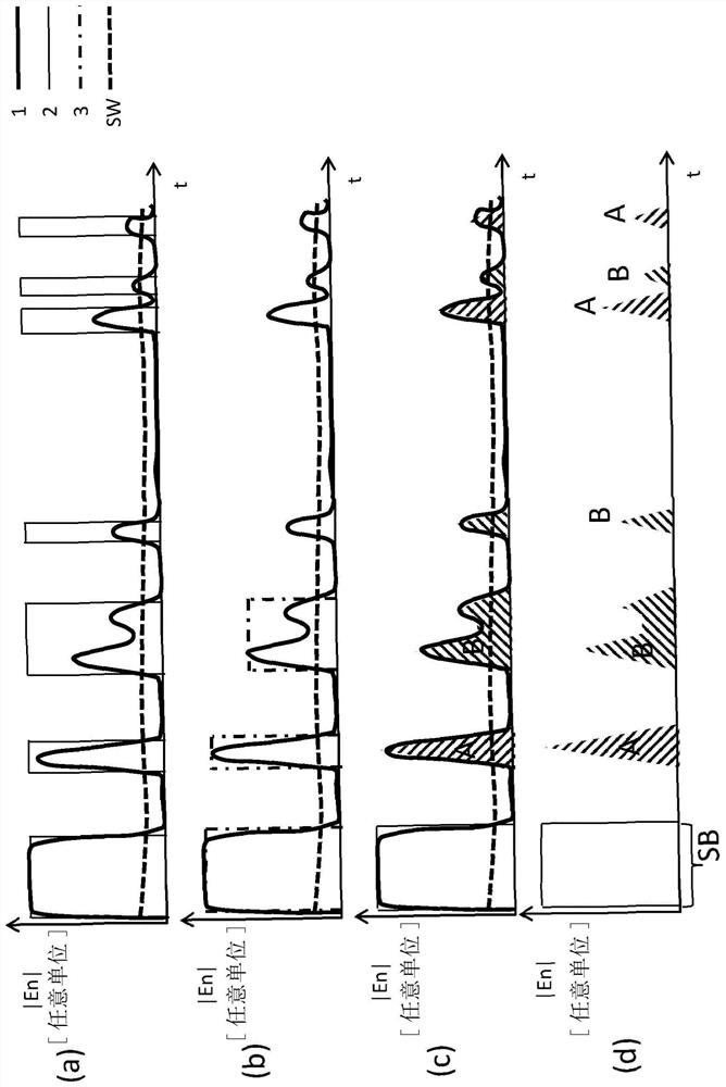
[0428] image 3 a shows the temporal profile of a conventional ultrasound echo signal 1 and its conventional evaluation in freely selectable units for the coordinate axes. It begins by sending out a transmit burst SB, carrying a threshold signal SW. Output 2 is set to logic 1 whenever the envelope signal of the ultrasound received signal (ultrasound echo signal 1 ) exceeds the threshold signal SW. Involves a time-analog interface with digital output levels. Then, a further evaluation takes place in the sensor's controller. Via this analog interface, which corresponds to the prior art, it is not possible to signal faults or control sensors.

[0429] image 3 b shows the time profile of a conventional ultrasound echo signal 1 and its conventional evaluation in freely selectable units for the coordinate axes. It begins by sending out a transmit burst SB, carrying a threshold signal SW. However, whenever the envelope signal of the ultrasound received signal (ultrasound echo ...


PUM

PropertyMeasurementUnit
strengthaaaaaaaaaa

Abstract

The invention relates to a method for operating an ultrasonic sensor, the associated sensor, the transmission of data to a computer system, and the associated decompression method in the computer system which controls the ultrasonic sensor. The compression method comprises the steps: detecting an ultrasonic received signal of an ultrasonic transducer, providing a signal-free ultrasonic echo signal model (610), carrying out at least once and optionally repeating a number of times the following steps of subtracting a reconstructed ultrasonic echo signal model (610) from the ultrasonic received signal (1) and forming a residual signal (660), the step of carrying out a method for recognising signal objects in the residual signal (660), supplementing the ultrasonic echo signal model (610) by the parameterised signal curve of a recognised signal object (600 to 605); and also ending the repetition of these steps if the values of the residual signal are below the values of a predetermined threshold signal. This is followed by transmitting at least some of the recognised signal objects in the form of symbols for these recognised signal objects to the computer system and using at least some of the recognised signal objects therein. These are preferably reconstructed in the computer system to give a reconstructed ultrasonic echo signal model.

Description

[0001] This patent application claims priority from German patent application 10 2019 106 204.7 of March 12, 2019, the content of which is hereby incorporated by reference as the subject of this patent application. technical field [0002] The present invention relates to a method for identifying obstacle objects and predicting changes in the position of known obstacle objects from the signals of a plurality of sensors and for compressing and decompressing the sensor signals used for the above-mentioned purpose, in particular A method for a vehicle for detecting the surroundings of the vehicle, as is provided, for example, in the context of parking assistance for the vehicle. [0003] In particular, the invention relates to a method and a corresponding device for transmitting data from an ultrasonic sensor system in a vehicle, for example for parking assistance, to a computer system (hereinafter also referred to as controller). The basic idea is to identify potentially importa...

Claims


Application Information

Patent Timeline
Patent Type & Authority Applications(China)
IPC IPC(8): G01S15/931G01S7/523G01S7/534G06N3/04G01N3/08
CPCG01S15/931G01S7/523G01S7/534G06N3/04G01N3/08G01S15/876G01S7/003G01S7/539G01S7/52001G01S13/862G01S7/533H03M7/30G01S7/417G01S15/86G01S15/66G01S17/66G01S17/931G01S2013/9324G01S2013/9323G01S13/723H03M7/3082G06N3/08G06N3/044G06N3/045
Inventor 丹尼斯·克里斯詹妮弗·杜丁
Owner ELMOS SEMICON SE
Why Eureka
Try Eureka