
Actuator, optical apparatus using actuator, and method of manufacturing actuator

a technology of actuators and actuators, applied in the direction of mountings, optics, instruments, etc., can solve the problems of complex driving mechanisms, difficult assembly of the driving mechanism of the lens barrel with the combination of the motor, the gear, etc., and the need for complex driving mechanisms, etc., to achieve the effect of low cos

Inactive Publication Date: 2006-02-09
ALPS ALPINE CO LTD
View PDF1 Cites 16 Cited by
  • Summary
  • Abstract
  • Description
  • Claims
  • Application Information

AI Technical Summary

Benefits of technology

[0013] The invention has been made in view of the conventional problems. It is therefore an object of the invention to provide an actuator having an external member with a movement hole, a movable body which moves within the movement hole, and a driving means for driving the movable body, and more particularly to provide the structure and operation of the actuator when the artificial muscle is used as the driving means.
[0015] By making each of the first driving member, the second driving member, and the third driving member of a high-polymer material having responsiveness to an electric field, the movable body can be moved within the movement hole of the external member rapidly and with a high driving force.
[0018] As described above, by repeating a series of operations including the first operation, the second operation and the third operation from the initial state by using an artificial muscle in which each of the driving members has the dielectric elastomer and the expandable or contractable electrodes, the movable body can be moved within the movement hole of the external member rapidly and with a high driving force. The structure of the driving members can be simplified by constructing each of the driving members with the dielectric elastomer and the expandable and contractable electrodes.
[0024] Further, in the aspect of the invention, preferably, the first to third driving members shares one dielectric elastomer, and a portion of the one dielectric elastomer corresponding to each of the driving members contracts partially in a predetermined direction. Thus, each of driving members can be driven at low cost.

Problems solved by technology

However, the driving mechanism for a lens barrel with the combination of the motor, the gear, etc. is difficult to be assembled into small electronic apparatuses, particularly, mobile telephones.
Further, in order to make the lens barrel perform various kinds of complex operations, an intricate driving mechanism is required.
As a result, not only an increase in size of the driving mechanism may be caused, but also an increase in manufacturing cost and a reduction in yield rate may be caused.
However, these actuators have problems in that expansion or contraction ratio is low, a high driving force cannot be obtained, the degree of freedom in structure is low, etc.
However, Patent Document 2 does not disclose using the artificial muscle as the driving mechanism for a lens barrel at all.

Method used


Image

  • Actuator, optical apparatus using actuator, and method of manufacturing actuator
  • Actuator, optical apparatus using actuator, and method of manufacturing actuator
  • Actuator, optical apparatus using actuator, and method of manufacturing actuator

Examples


Embodiment Construction

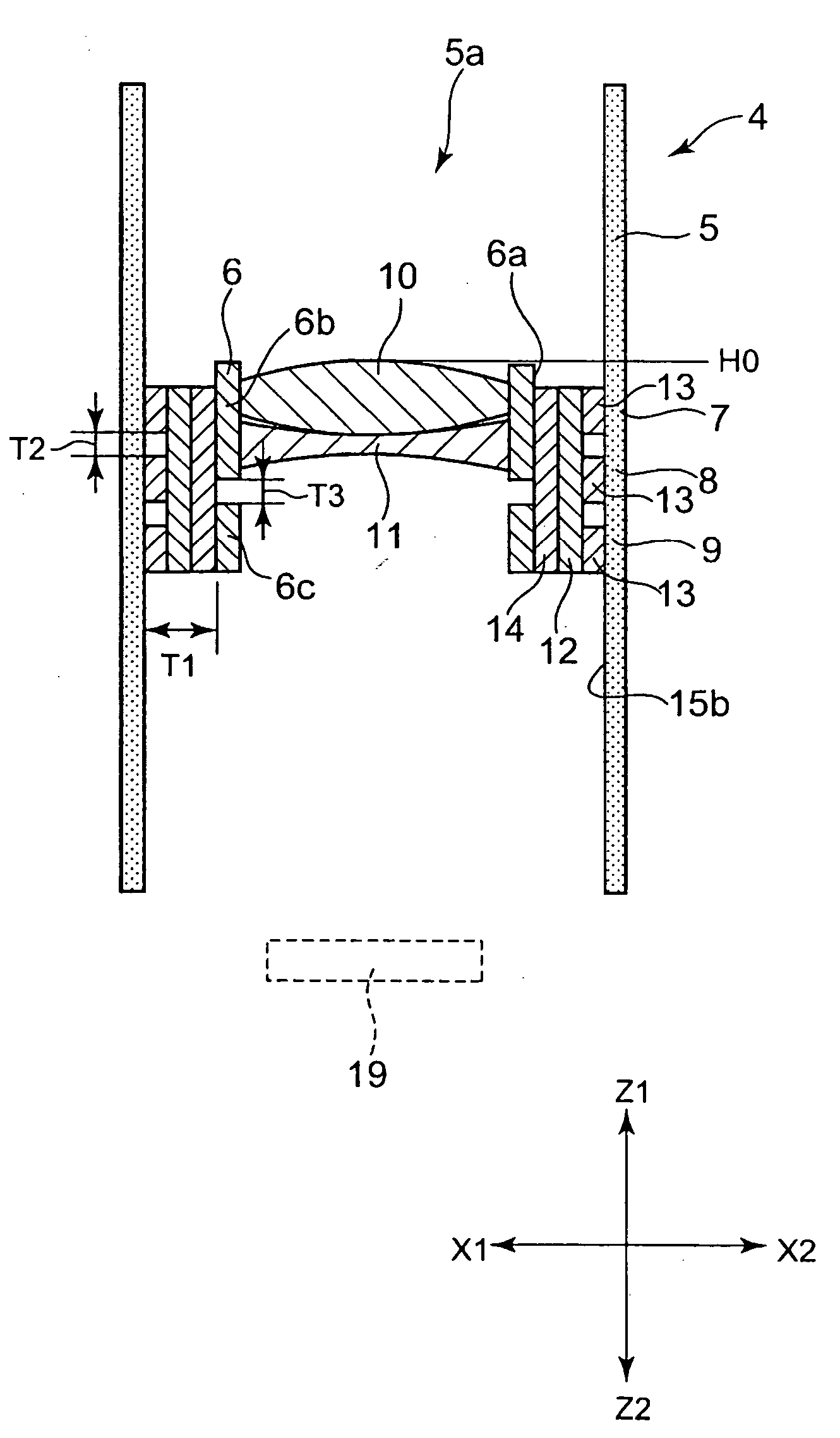
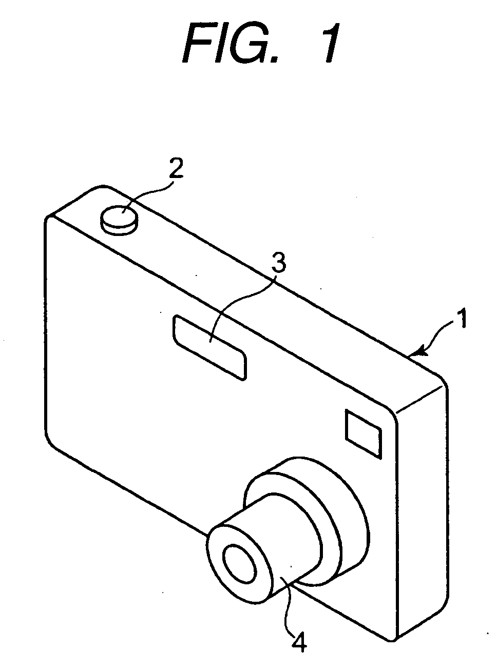
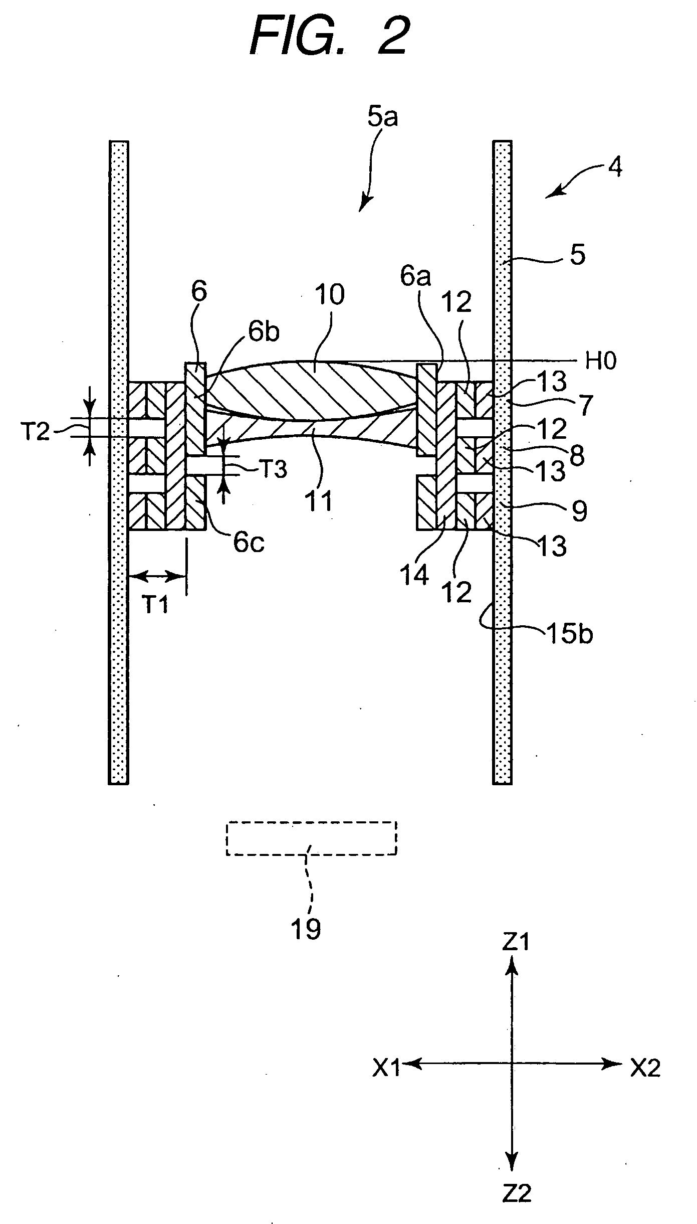
[0053]FIG. 1 is a partial perspective view showing the appearance of a digital camera using a lens driving mechanism (actuator) according the invention. FIGS. 2 to 6 are partial sectional view of an actuator according to a first embodiment of the invention, and explanatory views for explaining a series of operations of the actuator. FIG. 7 is a partial plan view of an actuator having another form of a driving part different from that of the driving part shown in FIG. 2. FIG. 8 is a partial plan view of the actuator shown in FIG. 2, as seen from above. FIG. 9 is a partial plan view of an actuator having another form of a driving part different from that of the driving part shown in FIG. 2. FIGS. 10 and 11 are partial sectional views of an actuator according to a second embodiment of the invention. FIGS. 12 to 15 are partial sectional view of an actuator according to a third embodiment of the invention, and explanatory view for explaining a series of operations of the actuator. FIG. 1...


PUM


Abstract

An actuator includes a holder having a movement hole, a lens barrel which moves within the movement hole, and driving means for driving the lens barrel. Each of the driving means is provided with driving members composed of an artificial muscle. The lens barrel can be suitably moved within the movement hole by making the driving members perform a predetermined operation.

Description

BACKGROUND OF THE INVENTION [0001] 1. Field of the Invention [0002] The present invention relates to an actuator used for, for example, optical apparatuses, etc. which have a holder with a movement hole and a lens barrel for accommodating the lens barrel, and which have a zooming function that the lens barrel moves within the movement hole, etc. [0003] 2. Description of the Related Art [0004] A driving mechanism for a lens barrel is disclosed inn FIG. 3 of Japanese Unexamined Patent Application Publication No. 5-249362 (hereinafter, referred to as Patent Document 1). Patent Document 1 discloses provision of an optical apparatus which can perform a focus-switching operation and a focusing operation with a single motor by a combination of the motor, a pinion, gear, etc. [0005] However, the driving mechanism for a lens barrel with the combination of the motor, the gear, etc. is difficult to be assembled into small electronic apparatuses, particularly, mobile telephones. [0006] Further,...

Claims


Application Information

Patent Timeline
IPC IPC(8): G02B7/02
CPCG02B7/08G02B7/023
Inventor YAMASHITA, TATSUMAROYOSHIYUKI, HITOSHIHAYASHI, MASAMICHIMATSUO, EIKI
Owner ALPS ALPINE CO LTD
Learn More