Frequency synthesizer architecture

Active Publication Date: 2006-02-09
MICROELECTRONIC INNOVATIONS LLC
View PDF9 Cites 12 Cited by
  • Summary
  • Abstract
  • Description
  • Claims
  • Application Information

AI Technical Summary

Benefits of technology

[0025] Embodiments of the present invention propose a frequency synthesizer of the fractional divider type, in other words with a digital algorithm in the loop capable of achieving a very good precision of the generated fre

Problems solved by technology

This means that a very large loop filter is required to keep the PLL stable.
But such a filter makes it impossible to use integratable solutions.
Note also that a low reference frequency makes it necessary to select high values N of the division ratio, which causes noise in the loop and degrades expected performances.
However, the sigma-delta modulator generates a high noise power in the loop that can cause undesirable fluctuations of the phase of the signal output by the voltage controlled oscillator.
However, if the

Method used


Image

  • Frequency synthesizer architecture
  • Frequency synthesizer architecture
  • Frequency synthesizer architecture

Examples


Example

DETAILED DESCRIPTION OF THE DRAWINGS

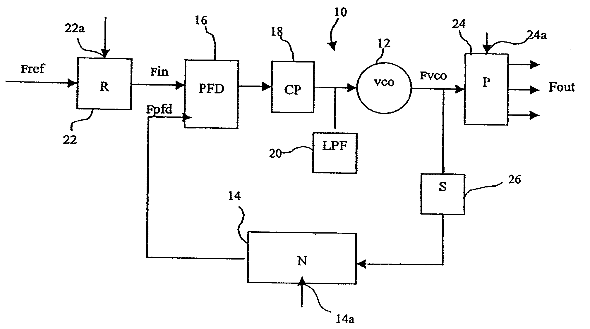
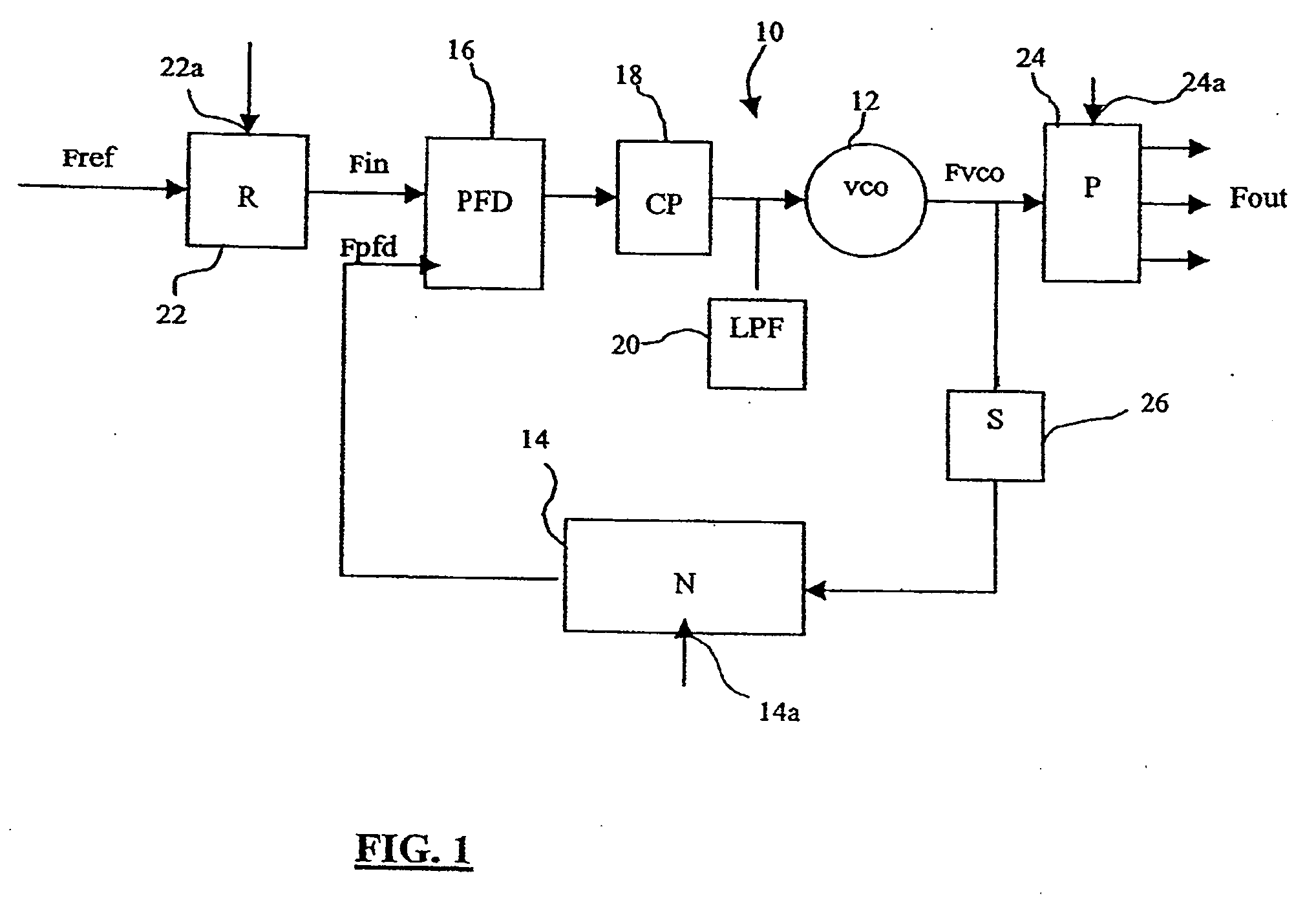
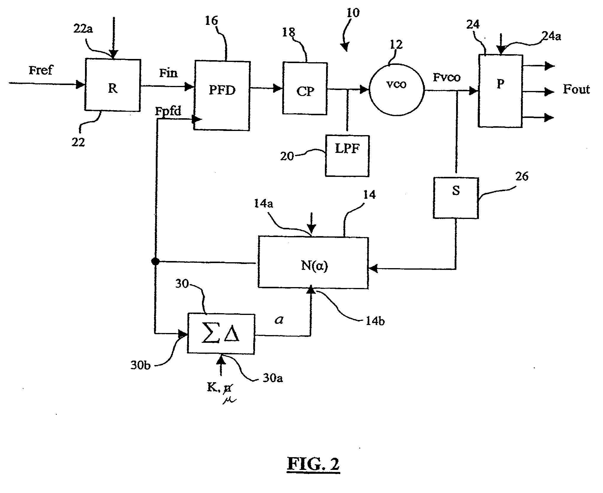
[0049] Therefore, FIG. 3 illustrates the diagram of a frequency synthesizer conform with this invention based on an improved fractional PLL by division. Elements in common with frequency synthesizers according to prior art already described are marked with the same references.

[0050] Thus, according to the invention, the phase locked loop now integrates particular modulation means 40 with a global modulation ratio β which, when multiplied by the frequency of the reference signal Fin applied to the first input of the phase comparator 16, produces the output frequency Fvco required at the output from the oscillator 12. As already seen with reference to the previous architectures, a frequency divider 22 may be inserted between a quartz device outputting a reference signal Fref and the phase comparator 16, such that the phase comparator compares the signal Fpfd with a frequency reference signal Fin determined by dividing the frequency of the signal F...


PUM


Abstract

A frequency synthesizer is provided with a PLL, including a divider by N circuit and a phase generation circuit which is connected to the output of the VCO of the PLL. The phase generation circuit generates a predetermined number of phases synchronized on the frequency of the VCO and at intervals from each other equal to a time difference representative of a phase error measured by a phase comparator of the PLL. A signal generation circuit provides an intermediate signal starting from the phases, the period of which is dependent on the time difference and a first adjustment parameter. The intermediate signal is applied to the divider by N circuit. A correction circuit determines the phase error accumulated during N−1 periods of the intermediate signal and makes a correction of the intermediate signal every N periods of the intermediate signal as a function of the accumulated phase error such that the loop becomes stable.

Description

PRIORITY CLAIM [0001] The present application claims priority from French Application for Patent No. 04 08737 filed Aug. 6, 2004, the disclosure of which is hereby incorporated by reference. BACKGROUND OF THE INVENTION [0002] 1. Technical Field of the Invention [0003] The present invention generally relates to domain of phase locked loops, and particularly phase locked loops made in the form of an integrated circuit and that are typically used in high frequency synthesis. More precisely, it concerns a frequency synthesizer enabling precise adjustment of the frequency, with a high signal-to-noise ratio and with advanced integration capabilities. [0004] 2. Description of Related Art [0005] A Phase Locked Loop (PLL) is generally widely used for frequency synthesis. This type of system is capable of multiplying a reference frequency by an integer number and thus addressing an entire frequency range with a given frequency step. More precisely, a phase locked loop is a slaving system gene...

Claims


Application Information

Patent Timeline
IPC IPC(8): H04B1/40H04B7/00H03L7/081H03L7/099H03L7/18
CPCH03L7/081H03L7/18H03L7/0996
Inventor GHAZALI, MOSTAFAPIERRE-OLIVIER, JOUFFRE
Owner MICROELECTRONIC INNOVATIONS LLC
Why Eureka
Try Eureka