Prosthetic foot with tunable performance

a prosthetic foot and tunable technology, applied in the field of high-performance prosthetic feet, can solve the problems of limited dynamic response characteristics of this known artificial foot, unable to mimic human biomechanical function, and prior art prosthetic feet with such designs produce only about 25% of normal ankle joint sagittal plane kinetic power, and achieve high performance and function. , the effect of improving the application of mechanics

Inactive Publication Date: 2006-02-09
BIOQUEST PROSTHETICS
View PDF24 Cites 33 Cited by
  • Summary
  • Abstract
  • Description
  • Claims
  • Application Information

AI Technical Summary

Benefits of technology

[0010] In order to allow the amputee to attain a higher level of performance and function, there is a need for a high performance prosthetic foot having improved applied mechanics, which foot can out perform the human foot and also out perform the prior art prosthetic feet. It is of interest to the amputee to have a high performance prosthetic foot having improved applied mechanics, high low dynamic response, and alignment adjustability that can be fine tuned to improve the horizontal and vertical components of activities which can be task specific in nature.

Problems solved by technology

However, the dynamic response characteristics of this known artificial foot are limited and do not mimic the human biomechanical function of the human foot, ankle and shank and soft supporting tissue.
The artificial foot of Martin et al. and other prior art prosthetic feet that utilize this ankle design and a rigid pylon as a shank cannot store enough elastic energy to create normal ankle joint sagittal plane kinetic power in gait.
Tests have shown that prior art prosthetic feet with such designs produce only about 25% of normal ankle joint sagittal plane kinetic power in gait.

Method used


Image

  • Prosthetic foot with tunable performance
  • Prosthetic foot with tunable performance
  • Prosthetic foot with tunable performance

Examples


Embodiment Construction

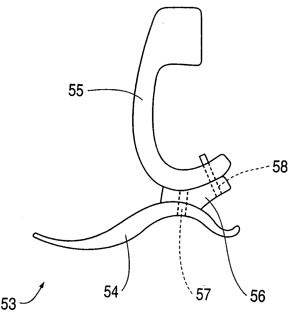
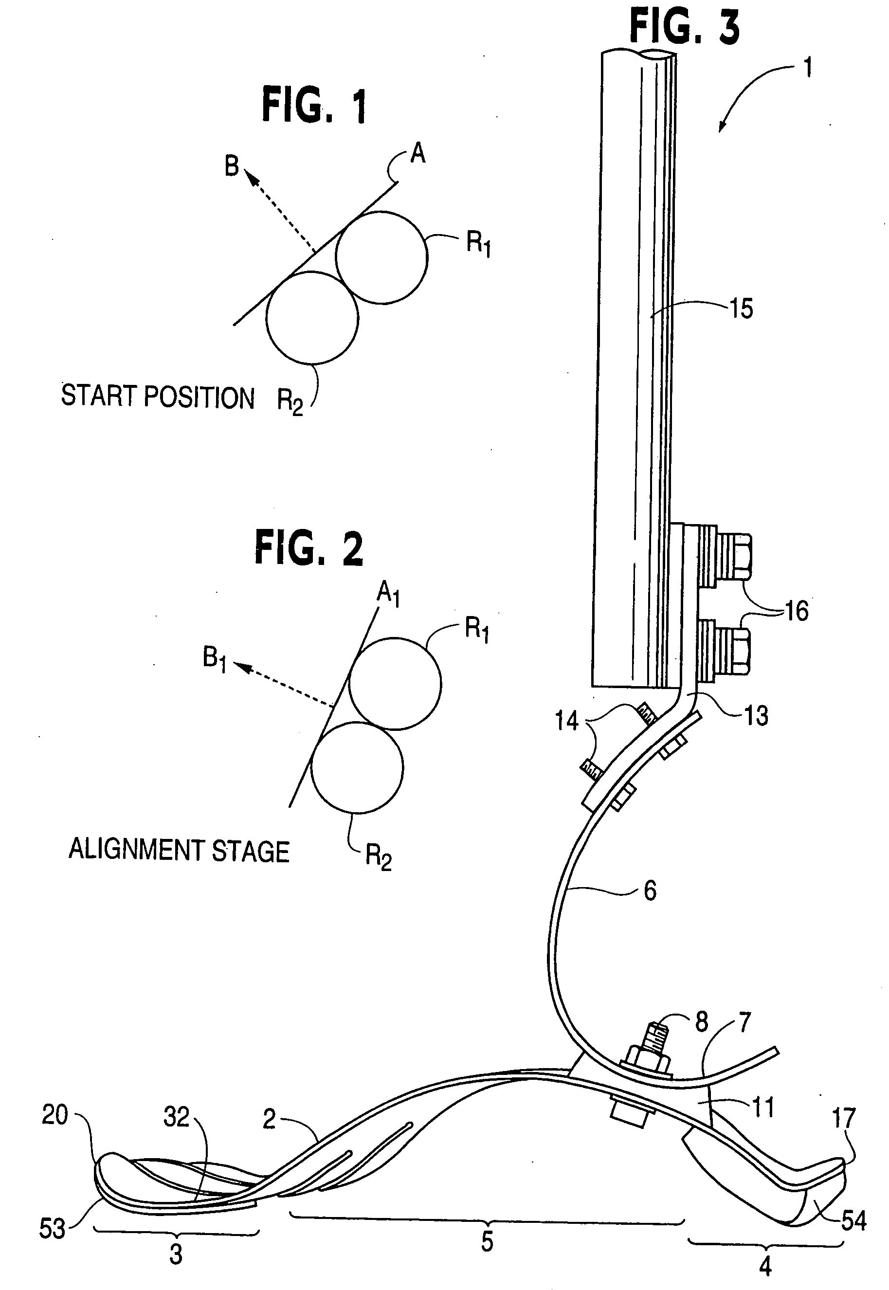
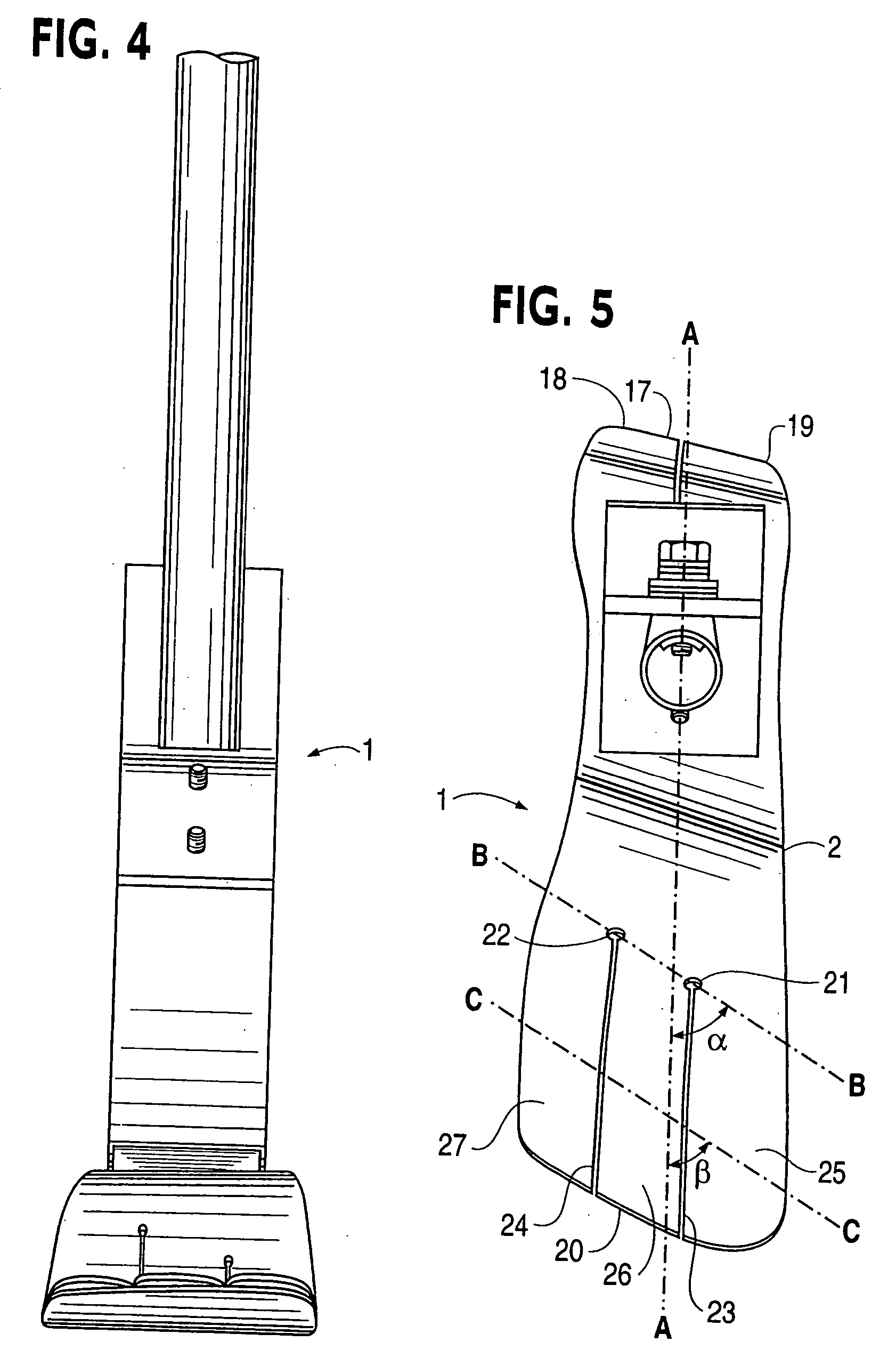
[0060] Referring now to the drawings, a prosthetic foot 1 in the example embodiment of FIGS. 3-5 is seen to comprise a longitudinally extending foot keel 2 having a forefoot portion 3 at one end, a hindfoot portion 4 at an opposite end and an upwardly arched midfoot portion 5 extending between the forefoot and hindfoot portions. The midfoot portion 5 is upward convexly curved over its entire longitudinal extent between the forefoot and hindfoot portions in the example embodiment.

[0061] An upstanding calf shank 6 of the foot 1 is attached at a portion of a downward convexly curved lower end 7 thereof to a proximate, posterior surface of the keel midfoot portion 5 by way of a releasable fastener 8 and coupling element 11. The fastener 8 is a single bolt with nut and washers in the example embodiment, but could be a releasable clamp or other fastener for securely positioning and retaining the calf shank on the foot keel when the fastener is tightened.

[0062] A longitudinally extending...


PUM


Abstract

A prosthetic foot (190) incorporates a foot keel (192) and a resilient calf shank (193) with its lower end connected to the foot keel to form an ankle joint of the prosthetic foot. The calf shank extends upward from the foot keel by way of an anterior facing convexly curved portion (195) of the shank, and is secured to the foot keel by way of a coupling element (194). The lower end of the shank is reversely curved (196) and housed by a reversely curved portion of the coupling element. A posterior calf device (191) has a cable (204) which is untensioned in a normal gait cycle but tensioned by a force loading on the prosthesis greater than 120% of body weight of the user to limit, e.g. stop, further anterior motion of the upper end of the shank.

Description

RELATED APPLICATIONS [0001] This application claims priority of International Applications Nos. PCT / US05 / 011304 and PCT / US05 / 11291, each filed Apr. 1, 2005 and designating the U.S. [0002] This application is a continuation in part application of each of the following applications: [0003] (1) International Application No. PCT / US02 / 09589 filed Mar. 29, 2002 and designating the U.S. and the related U.S. national stage application Ser. No. 10 / 473,682 filed Sep. 30, 2003, which is a continuation in part of U.S. application Ser. No. 09 / 820,895 filed Mar. 30, 2001, now U.S. Pat. No. 6,562,075 issued May 13, 2003. [0004] (2) International Application No. PCT / US05 / 011902 filed Apr. 1, 2005 and claiming priority of U.S. Application No. 60 / 558,119 filed Apr. 1, 2004. [0005] (3) U.S. application Ser. No. 10 / 814,260 filed Apr. 1, 2004 which is a continuation in part of U.S. application Ser. No. 10 / 263,795 filed Oct. 2, 2002, which is a continuation of U.S. application Ser. No. 09 / 820,895 filed M...

Claims


Application Information

Patent Timeline
Patent Type & Authority Applications(United States)
IPC IPC(8): A61F2/66A61F2/00A61F2/60A61F2/50A61F2/68A61F2/70A61F2/74A61F2/76A61K9/48
CPCA61F2/60A61K9/4816A61F2/6607A61F2/76A61F2002/30433A61F2002/30434A61F2002/30438A61F2002/30464A61F2002/30466A61F2002/5001A61F2002/5003A61F2002/5006A61F2002/5007A61F2002/5009A61F2002/503A61F2002/5032A61F2002/5033A61F2002/5075A61F2002/5079A61F2002/5083A61F2002/607A61F2002/6614A61F2002/6621A61F2002/6628A61F2002/6635A61F2002/6642A61F2002/665A61F2002/6657A61F2002/6664A61F2002/6671A61F2002/6678A61F2002/6685A61F2002/704A61F2002/745A61F2002/747A61F2002/7615A61F2220/0041A61F2220/0075A61F2/66A61F2002/30462A61F2/74
Inventor TOWNSEND, BARRY W.CLAUDINO, BYRON KENT
Owner BIOQUEST PROSTHETICS
Why Eureka
Try Eureka