
Courtesy pump

a courtesy pump and odor removal technology, applied in water installations, construction, domestic applications, etc., can solve the problems of not being able to effectively remove the same odor, and removing the entire air volume from the bathroom to remove the odorous

Inactive Publication Date: 2006-02-16
JOHNSON LESTER GASTON
View PDF3 Cites 9 Cited by
  • Summary
  • Abstract
  • Description
  • Claims
  • Application Information

AI Technical Summary

Benefits of technology

[0004] In view of the aforementioned disadvantages inherent in existing apparatus for dealing with odors produced by bathroom usage, the present invention provides a COURTESY PUMP wherein the same can be utilized to remove odors produced by bathroom usage before same odors are allowed to mix with the general air volume in the bathroom.
[0005] The bathroom courtesy pump apparatus takes the approach of confirming odors to the bowl area; as they are produced, thereby preventing them from escaping into and fouling the overall air volume in the bathroom area and adjoining rooms. The courtesy pump's explicit approach is to first confine the fouled air to the bowl, then subsequently extract the confined air to a controlled area, remove the odors, apply fragrance to the filtered air and return the refreshed air either to the general air volume in the room, or back to bowl area; never allowing the odor producing gases to be detected by the user or others present in the bathroom.
[0013] It is another object of the present invention to provide a COURTESY PUMP with reduced the size, weight and cost of operation compared to existing devices removing odor-causing gases from bathrooms.
[0014] It is another object of the present invention to provide a COURTESY PUMP which may be easily and efficiently manufactured.
[0015] Event still another object of the invention is to provide a COURTESY PUMP apparatus that which includes a simple or compound housing containing mechanism for removing odor-causing gases from an air volume, a mechanism for forcing air to move from one location to another and a mechanism for adding fragrance to air passing through the housing; a containment ring and extraction tube resides outside of same housing.

Problems solved by technology

Additionally removing the entire air volume from the bathroom to remove the odorous as is done in prior art is not an efficient means of removing same odor.

Method used


Image

  • Courtesy pump
  • Courtesy pump
  • Courtesy pump

Examples


Embodiment Construction

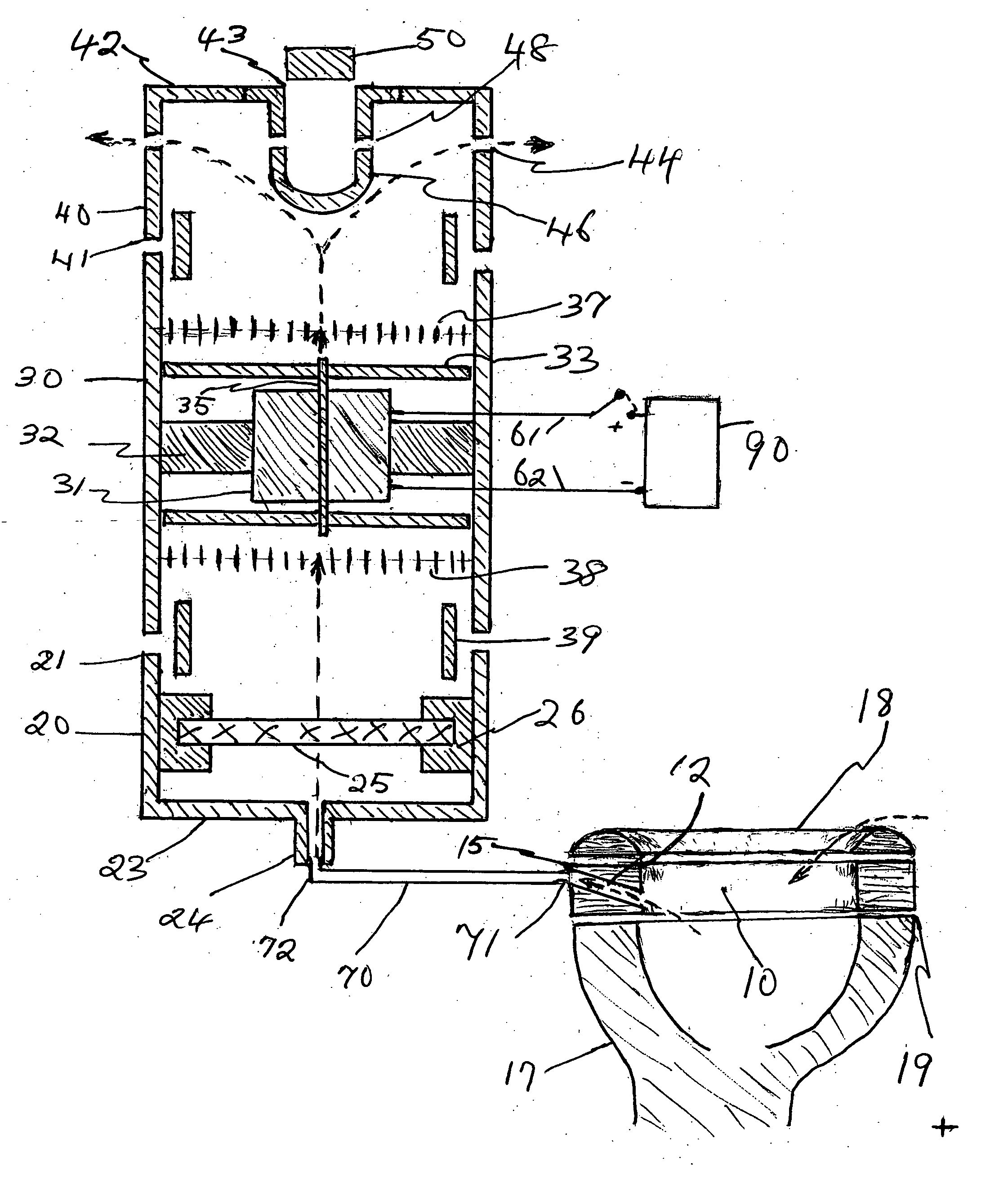
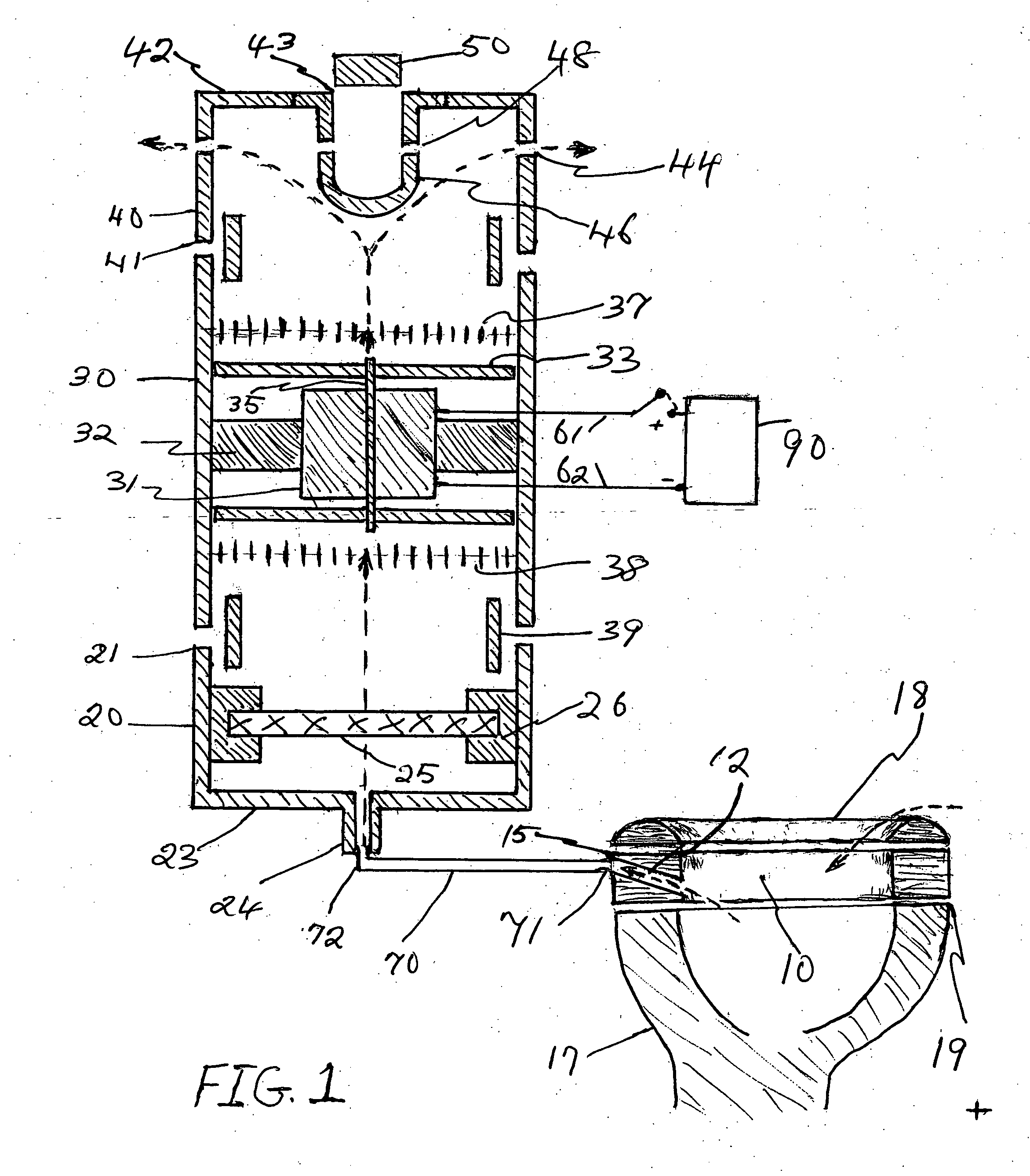
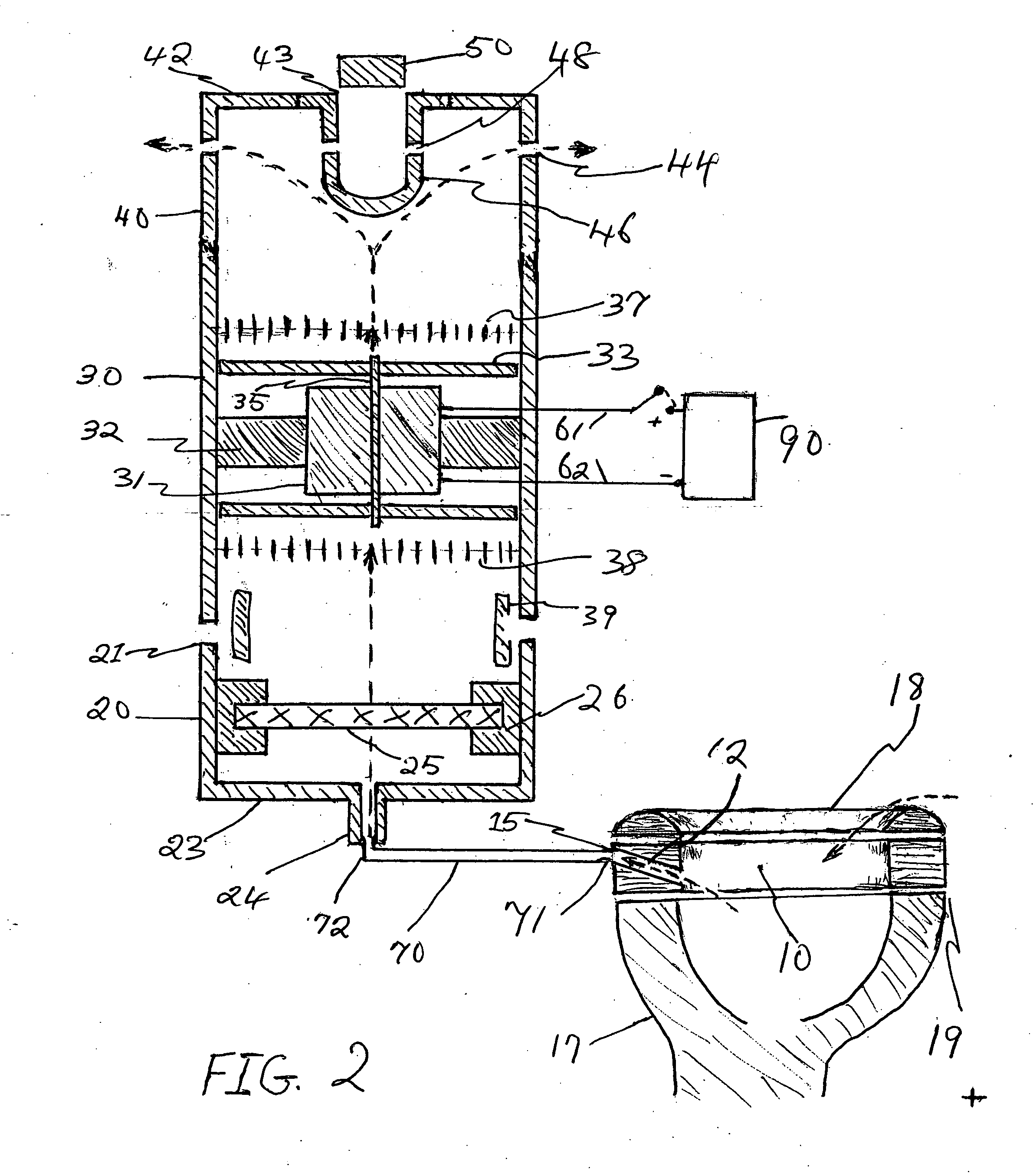
[0020] With reference now to the drawings, and in particular to FIGS. 1 through 2 thereof, a COURTESY PUMP embodying the principles and concepts of the present invention and generally designated by the reference numeral # will be described.

[0021] As shown in FIG. 1, a housing having a plurality of sections 40, 30, and 20 and providing a continuous enclosed interior space when sections are joined together via sleeves 39.

[0022] The core component of the courtesy pump is the extractor. Referring to FIG. 1, the extractor is made up of a housing section 30, a centrally placed motor 31, motor mounts 32, and fan blades 33. The fan blades are fitted to the top end of the motor shaft 35; or at both ends of the shaft to generate stronger suction. Once assembled, the fan-motor assembly is attached to motor mounts #32 and the entire fan-motor complex inserted into the extractor housing section 30. Electrical leads 61 and 62 are passed from the motor through air-tight seals in the housing to a...


PUM


Abstract

The present invention provides device for cleaning air fouled by bathroom usage, and more particularly an air cleaning device having: a housing for holding air extraction mechanism, air filtration mechanism, mechanism for germicidal treatment of air, and air refreshing mechanism; a foul air containment ring mechanism; an extractor tube mechanism connecting containment ring to filtration mechanism. The containment ring mechanism confines air fouled by bathroom usage from escaping the bowl area and using with air breathe by user. The extractor mechanism forces the confined fouled air to the filtration mechanism through the extractor tube. Odor causing molecules along with bacterial and viral bodies are removed at the filtration mechanism. The extractor mechanism subsequently forces the filtered air through the refresher mechanism where fragrances are added to the air before the air is returned to the room's air mass.

Description

BACKGROUND OF THE INVENTION [0001] The present invention relates to bathroom odors, and more particularly pertains to a new COURTESY PUMP for removing odors produced by bathroom usage. [0002] Bathroom usage often times produce odors which are unpleasant to the user as well as others present in the bathroom. Various strategies have been employed to eliminate such odors. Prior art approaches have been either to mask the odors and allow the air to remain in the room, or to remove the entire air volume from the room to eliminate the offending odor. In both these approaches however, the odorous air is dealt with only after said odorous air has escaped the bowl area and moved into the room's general air volume. Such odors therefore are allowed to affect the user and others present before said odors could be masked by sprays or other fragrance dispensers, or removed from the room by exhaust fans of one type or another. Additionally removing the entire air volume from the bathroom to remove...

Claims


Application Information

Patent Timeline
IPC IPC(8): E03D9/04
CPCE03D9/05A47K13/307
Inventor JOHNSON, LESTER GASTON
Owner JOHNSON LESTER GASTON
Learn More