
Breading machine

a breading machine and breading technology, applied in the field of food product breading machines, can solve the problems of flaccid products only partially breaded, uneven coating, and affecting the breading quality of the product, and achieve the effects of reducing the breading quality, and improving the breading quality

Active Publication Date: 2006-02-16
BETTCHER INDUSTRIES
View PDF36 Cites 16 Cited by
  • Summary
  • Abstract
  • Description
  • Claims
  • Application Information

AI Technical Summary

Benefits of technology

[0018] In one exemplary embodiment, a drive and driven shafts engage each other by a floating coupling that allows slight misalignment in mutually orthogonal directions. This improved engagement structure permits engagement of the drive and driven shafts while the machine drive is running.

Problems solved by technology

Flaccid and frangible products, like fish filets, chicken tenders, and croquettes, presented problems.
Consequently, some flaccid products were only partially breaded while others were unevenly coated.
The machine had a relatively large footprint and required the attendant to load items into the end of the machine that was opposite from the discharge end.
Another problem with the prior art breading units was that after breading material was applied, the food products often carried breading material that was either loose, or only weakly adhered to the product.
This material was sometimes later be adhered to food products during frying, creating unappealing appearance and flavor.
Unloading breading material from prior art breading machines has sometimes been difficult.
This system works well in eliminating the breader reservoir from moving side-to-side axially but does nothing for supporting the breader load vertically.
Also the latch had a tendency to ride up out of its groove causing the breader to become disengaged during operation, resulting in break in production.

Method used


Image

  • Breading machine
  • Breading machine
  • Breading machine

Examples


Embodiment Construction

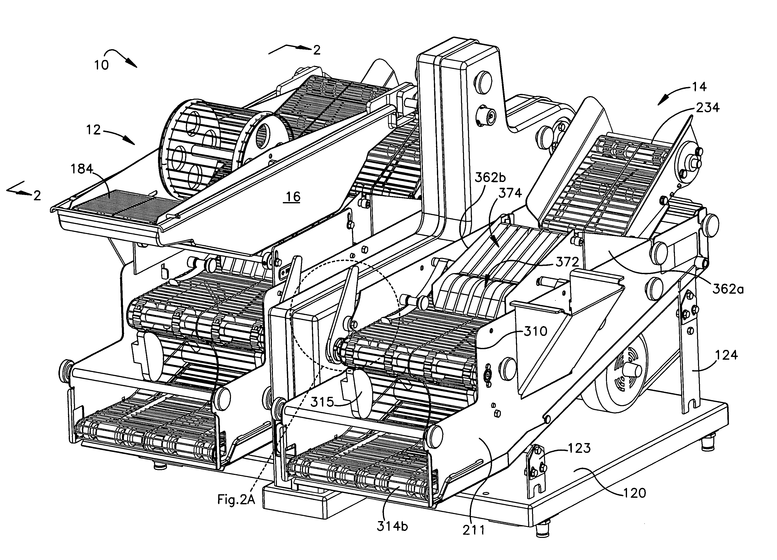
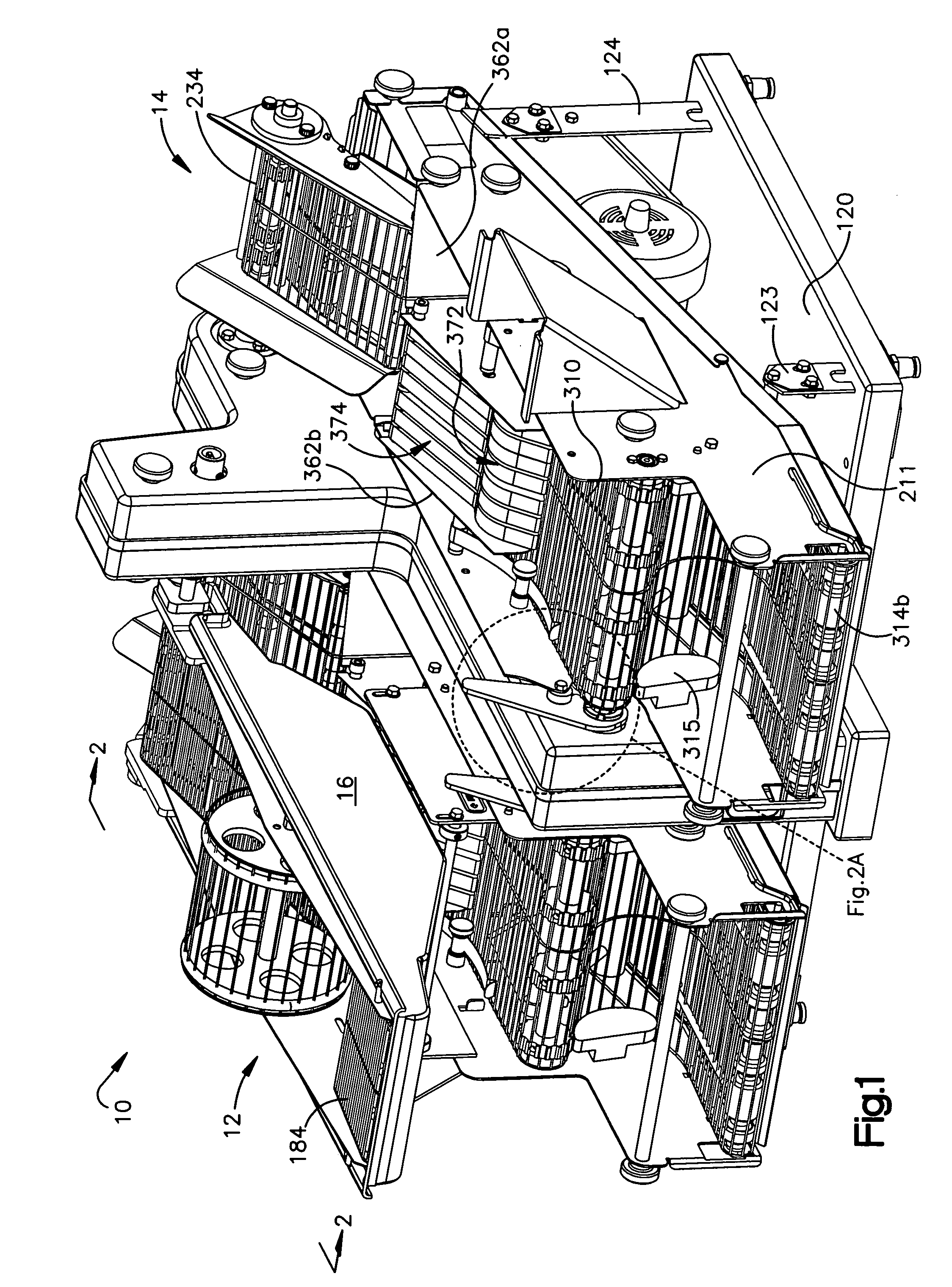
[0045] A food product breading machine 10 constructed according to the invention is illustrated in the drawings. The machine 10 is especially useful in restaurants where individual food products that are flaccid, such as chicken tenders, fish filets, etc., or frangible, such as croquettes, are fried to order. The machine 10 coats individual food items with a fluent batter and then overcoats them with a particulate breading material that clings to the batter. The breaded items are discharged from the machine in condition for frying.

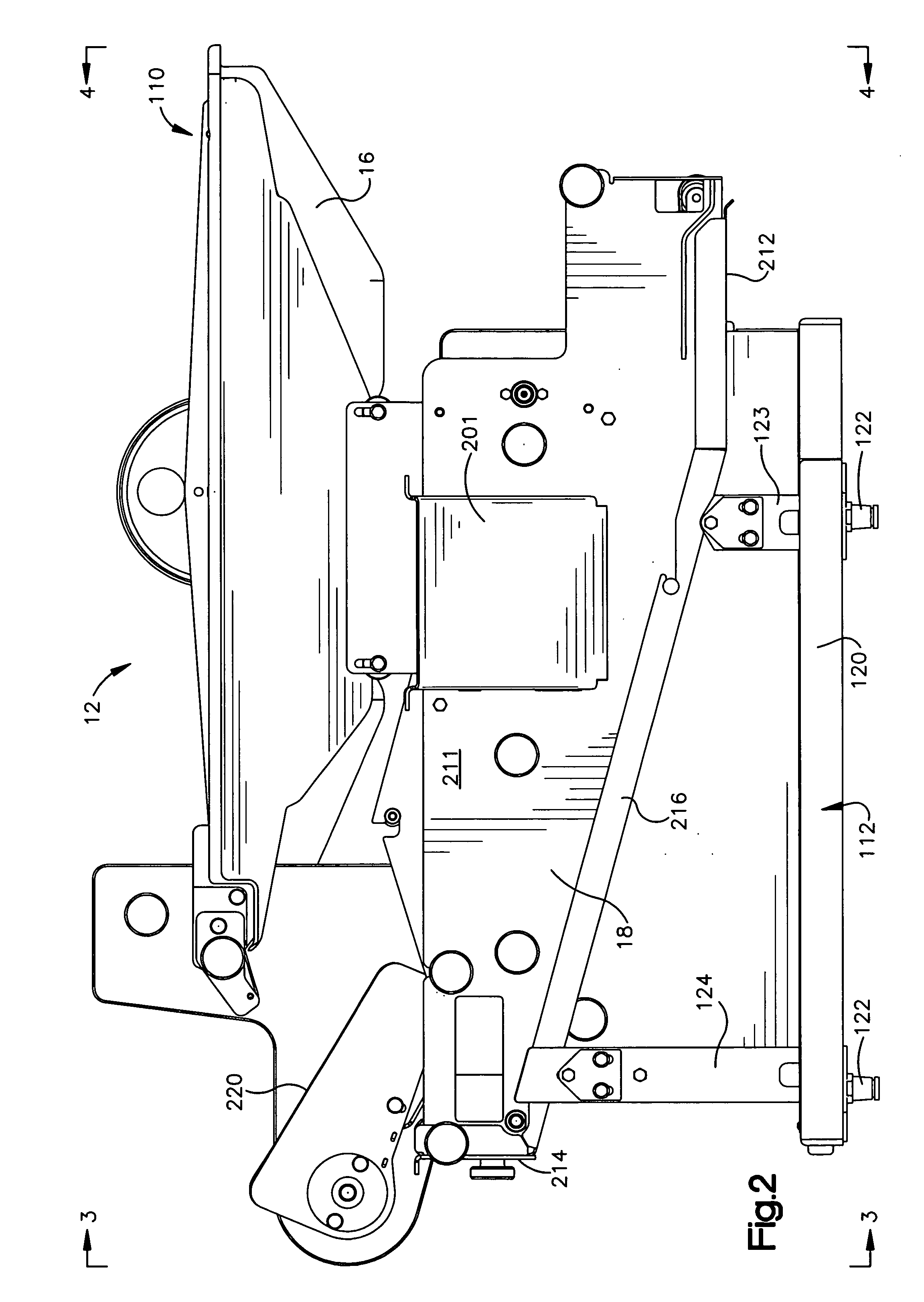
[0046] The exemplary embodiment of the invention depicted in FIGS. 1-4 is a breading machine 10 that has first and second combination battering / breading units 12, 14 positioned in close proximity to each other. In the exemplary embodiment of the invention the units 12, 14 are positioned in side by side relation to each other.

[0047] Each of the combination units 12, 14 has a battering unit 16 for applying a fluent batter to a food product. The battering u...


PUM


Abstract

A breading machine has a battering unit for applying a fluent batter to a food product. The battering unit includes a batter reservoir and a battering unit conveyor system for delivering food products from said batter reservoir to a battering unit conveyor discharge section that propels the food product from the battering unit. The combination units also include a breading unit for receiving food product from an associated battering unit. The breading unit includes a breading reservoir and breading unit conveyor system for applying particulate breading to the food product at a breading station by moving breading material from the breading material reservoir and food product coated with the batter to the breading station. A conveyor drive system includes a machine housing and a drive unit rotatably supported by the machine housing that provides motive power to the breading unit conveyor. A breading unit drive is coupled to the breading unit conveyor and is rotated by the drive unit to move said breading unit conveyor.

Description

RELATED APPLICATION [0001] The present application is a continuation in part application of Co-Pending U.S. patent application Ser. No. 10 / 856,248, filed May 28, 2004, which claims priority from pending U.S. provisional application Ser. No. 60 / 498,919 entitled “Improved Breading Machine” that was filed in the U.S. Patent and Trademark office on Aug. 29, 2003.FIELD OF THE INVENTION [0002] The present invention relates to food product breading machines and more particularly to food product breading machines that are used to coat flaccid products with particulate breading materials. BACKGROUND OF THE INVENTION [0003] Flaccid food products, such as fish filets and chicken tenders, and delicate, frangible products, like croquettes, are typically breaded and fried for consumption by restaurant customers. These products, together with other foods that are fried, are frequently produced and consumed in volumes sufficient to justify in-restaurant use of machinery that batters and then coats ...

Claims


Application Information

Patent Timeline
IPC IPC(8): A23B4/02A23L7/157A23P1/08
CPCA23P1/082A21C9/04A23P20/12
Inventor MUNIGA, SCOTT M.WHITED, JEFFREY A.BETTCHER, LANE
Owner BETTCHER INDUSTRIES
Learn More