Optical pickup

An optical pickup and light splitting technology, which is applied in the direction of instruments, beam reproduction, optical recording heads, etc., can solve the problems of increasing the number of polarization splitting elements, difference in response performance, increase in consumed electric power, etc., and achieve the effect of reducing noise

Inactive Publication Date: 2005-04-27
SHARP KK
View PDF1 Cites 1 Cited by
  • Summary
  • Abstract
  • Description
  • Claims
  • Application Information

AI Technical Summary

Problems solved by technology

Therefore, for devices requiring saving of electric power, such as mobile devices, the use of the above-mentioned active phase compensating element is disadvantageous due to the increase of electric power consumed due to the electric power used for driving and control.
[0006] Furthermore, in a structure having an active phase compensating element, a servo signal and a reproduced signal are received in a single optical path (hereinafter, the reproduced signal will be referred to as a magneto-optical signal), there is a case where the response required for servo signal detection performance and the response performance required for magneto-optical signal detection
In this case, the design standard is introduced as a stricter standard, so there is a problem that the performance and size limitations of the light receiving part become strict, and the tolerance required for the optical system also becomes strict
In addition to this, connection with an external driving device becomes necessary, so there arises a problem that it is difficult to integrate an electrically driven phase compensating element with some other structural elements of an optical pickup
[0007] It is also possible to consider a method of receiving the servo signal and the magneto-optical signal in separate optical paths, however, when only using a polarization splitting element having the same polarization splitting performance and changing the splitting path of each magneto-optical recording medium to receive light In the case of , corresponding to the different arrival points of the light beam after branching, polarization beam splitting elements must be placed for the respective optical path branches, so there is a problem that the number of polarization beam splitting elements is increased unnecessarily

Method used


Image

  • Optical pickup
  • Optical pickup
  • Optical pickup

Examples


Embodiment Construction

[0063] Referring now to the accompanying drawings, preferred embodiments of the present invention will be described below.

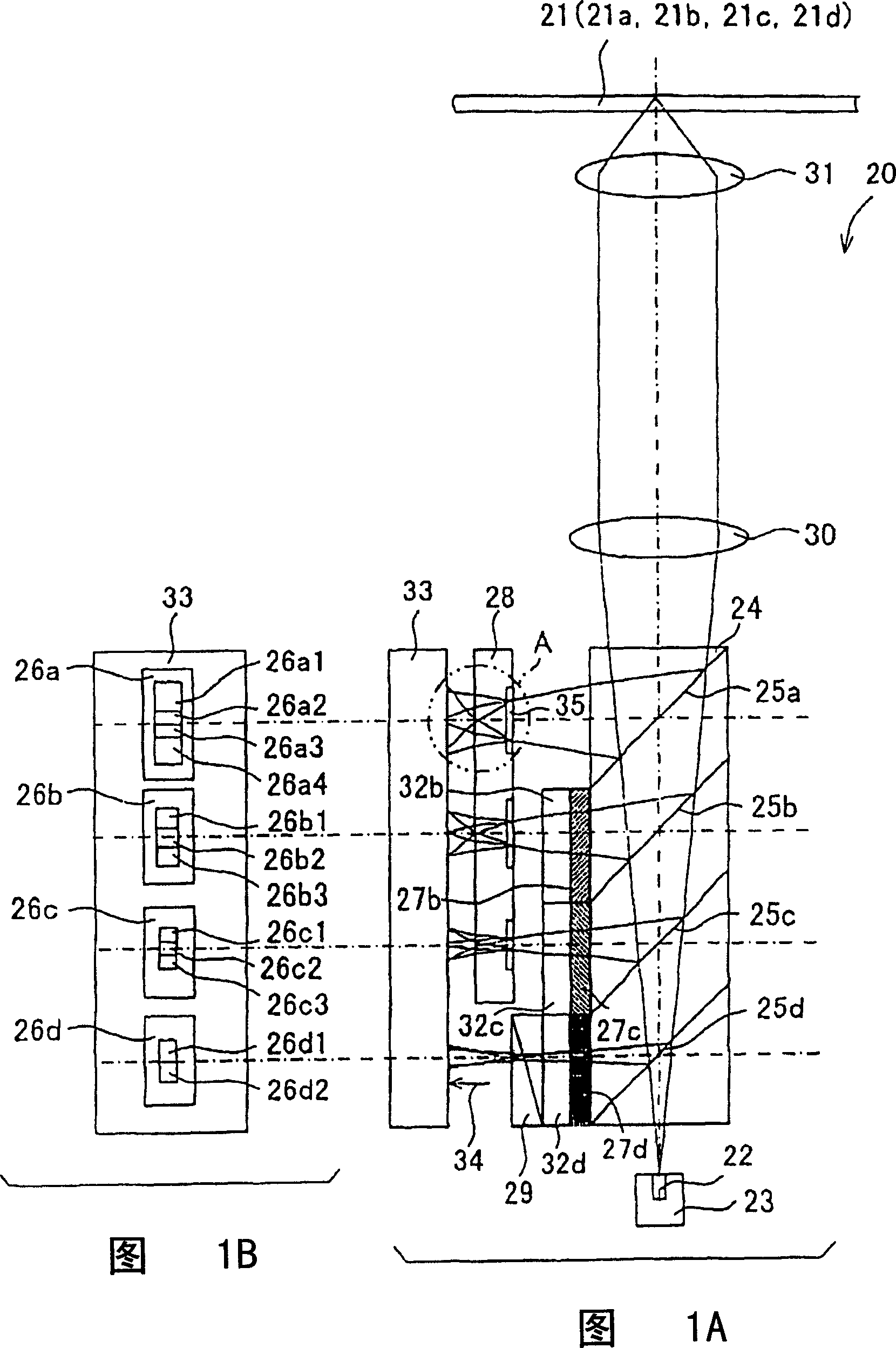
[0064] FIG. 1A is a simplified system diagram showing the structure of an optical pickup 20 according to a first embodiment of the present invention. The optical pickup 20 is a device for recording information and / or reproducing information on and / or from a plurality of (in this embodiment, four kinds of 21a, 21b, 21c and 21d) magneto-optical recording media 21, the magneto-optical recording media 21 has an information recording layer composed of a multi-layer film, and in which phase differences between polarized light beams generated at the time of signal reproduction are different from each other.

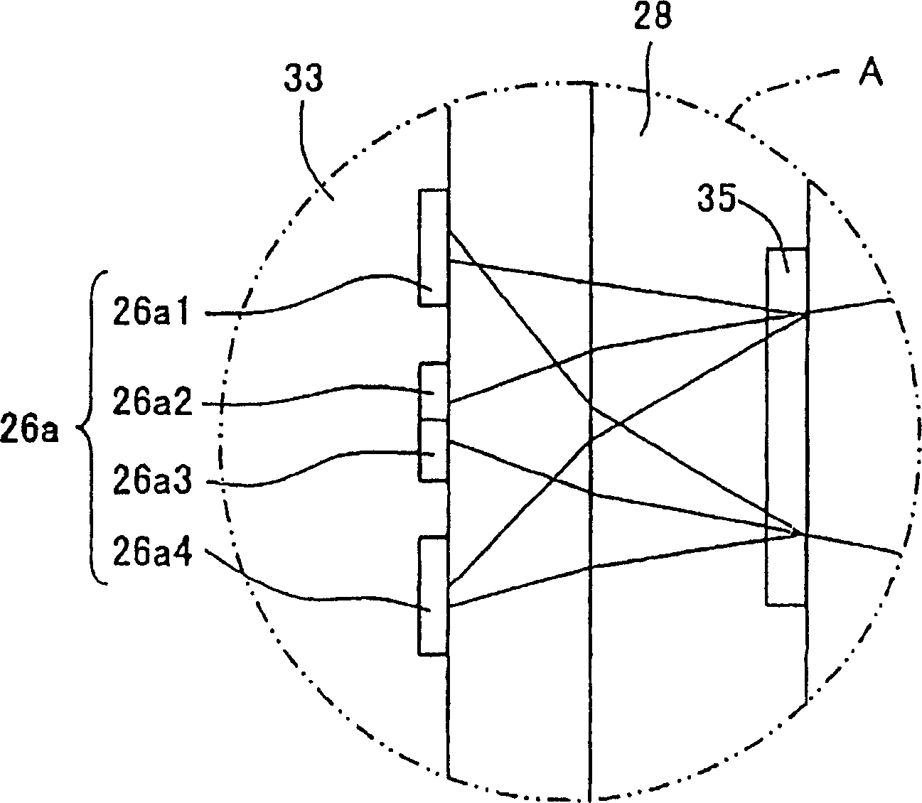
[0065]The optical pickup 20 includes a light source 22, a subassembly stage 23, a light splitting element 24, four groups of light receiving parts 26a, 26b, 26c and 26d, three phase compensating devices 27b, 27c and 27d, first and second two polarization s...


PUM


Abstract

A light branching element which branches a light beam emitted from a light source and reflected on a magneto-optical recording medium is provided with four light branching portions, and three phase compensating means which give a fixed phase deltaM to a light beam branched by an M-th (M=2 to 4) light branching portion is disposed on paths of light beams branched by the three light branching portions except the first light branching portion of the four light branching portions. In this optical pickup, servo signals of four kinds of optical recording mediums are respectively detected using light beams detected by three or less groups of light receiving portions selected from among four groups of light receiving portions.

Description

technical field [0001] The present invention relates to an optical pickup for recording information on and / or reproducing information from a magneto-optical recording medium. Background technique [0002] In order to expand the recording amount of information, in the magneto-optical recording medium that records information on the recording medium using light and magnetism, the so-called protrusion / depression of recording information on and / or reproducing information from protrusions and grooves is performed. Groove recording, or multilayer film recording where the information recording surface is made into multiple layers. However, magneto-optical recording media performing land / groove recording or multilayer film recording sometimes cause phase transitions that differ from each other between polarized light beams generated by reflection of the magneto-optical recording medium at the time of signal reproduction. Even when such a phase change between polarized beams occurs,...

Claims


Application Information

Patent Timeline
Patent Type & Authority Applications(China)
IPC IPC(8): G11B7/09G11B7/135G11B7/1356G11B7/1365G11B11/10G11B11/105
CPCG11B7/1365G11B11/10545G11B7/1356
Inventor 南功治上山徹男三宅知之中田泰男
Owner SHARP KK
Why Eureka
Try Eureka