Flat tube exhaust heat exchanger with bypass

a heat exchanger and flat tube technology, applied in the field of heat exchangers, can solve problems such as compactness or space-saving, and achieve the effects of reducing production costs and improving efficiency

Active Publication Date: 2006-02-16
MODINE MFG CO
View PDF4 Cites 32 Cited by
  • Summary
  • Abstract
  • Description
  • Claims
  • Application Information

AI Technical Summary

Problems solved by technology

However, it will be appreciated by those skilled in the art that the entire system (vehicle with internal combustion engine) and an overall energy balance are at issue.
Such heat exchangers are a special design which is not particularly compact or space-saving, and therefore disadvantageous in that respect if used in vehicle engine compartments where space is limited.

Method used


Image

  • Flat tube exhaust heat exchanger with bypass
  • Flat tube exhaust heat exchanger with bypass
  • Flat tube exhaust heat exchanger with bypass

Examples


Embodiment Construction

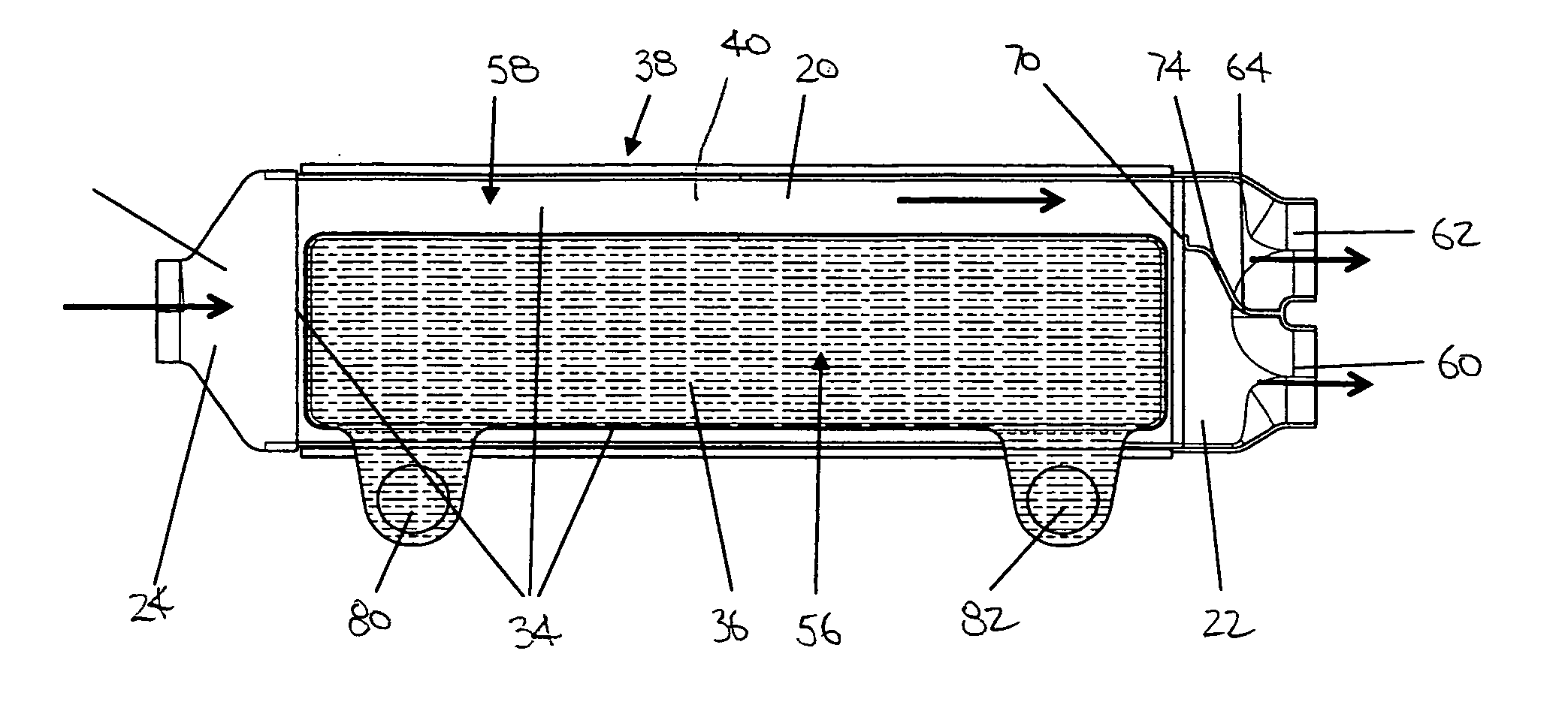
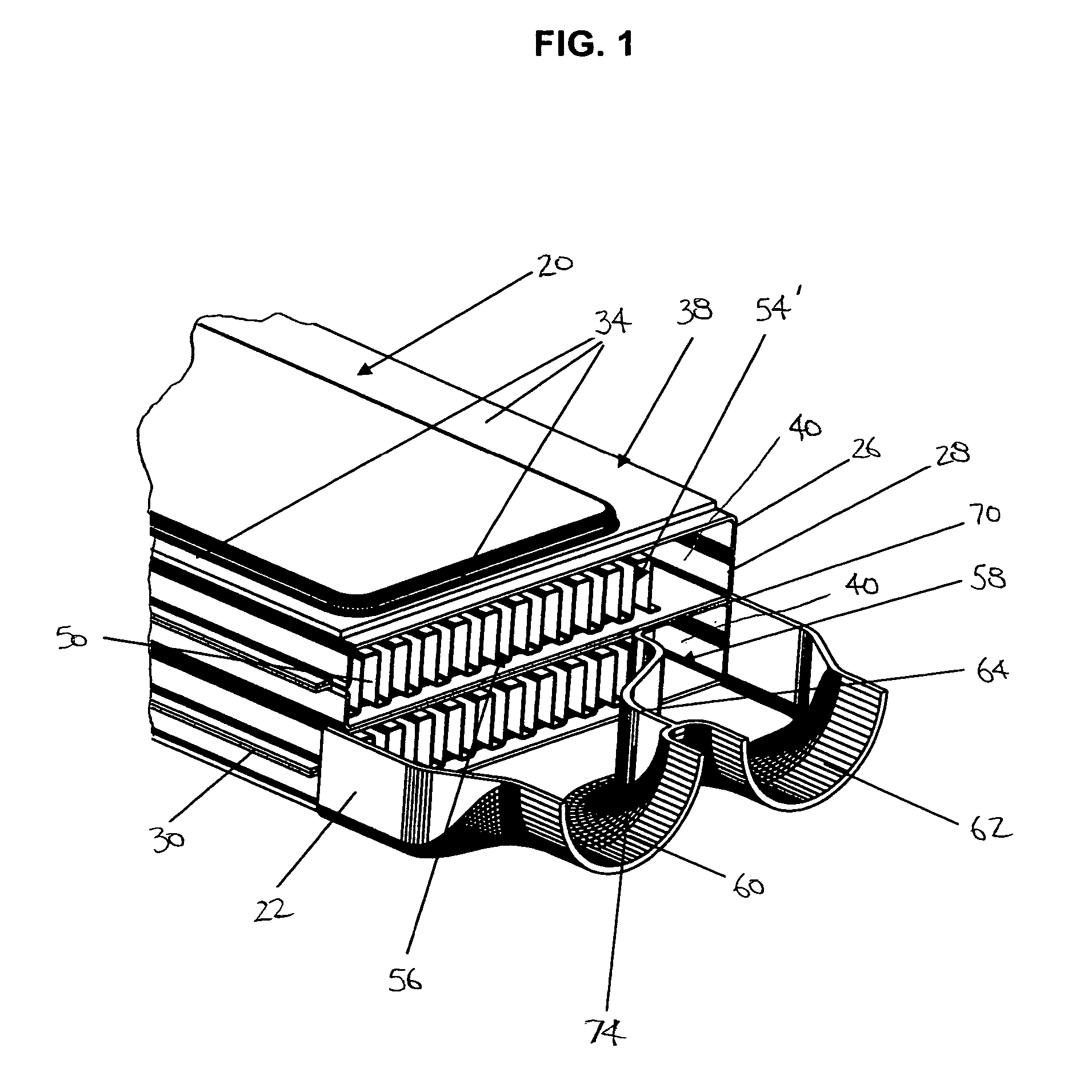
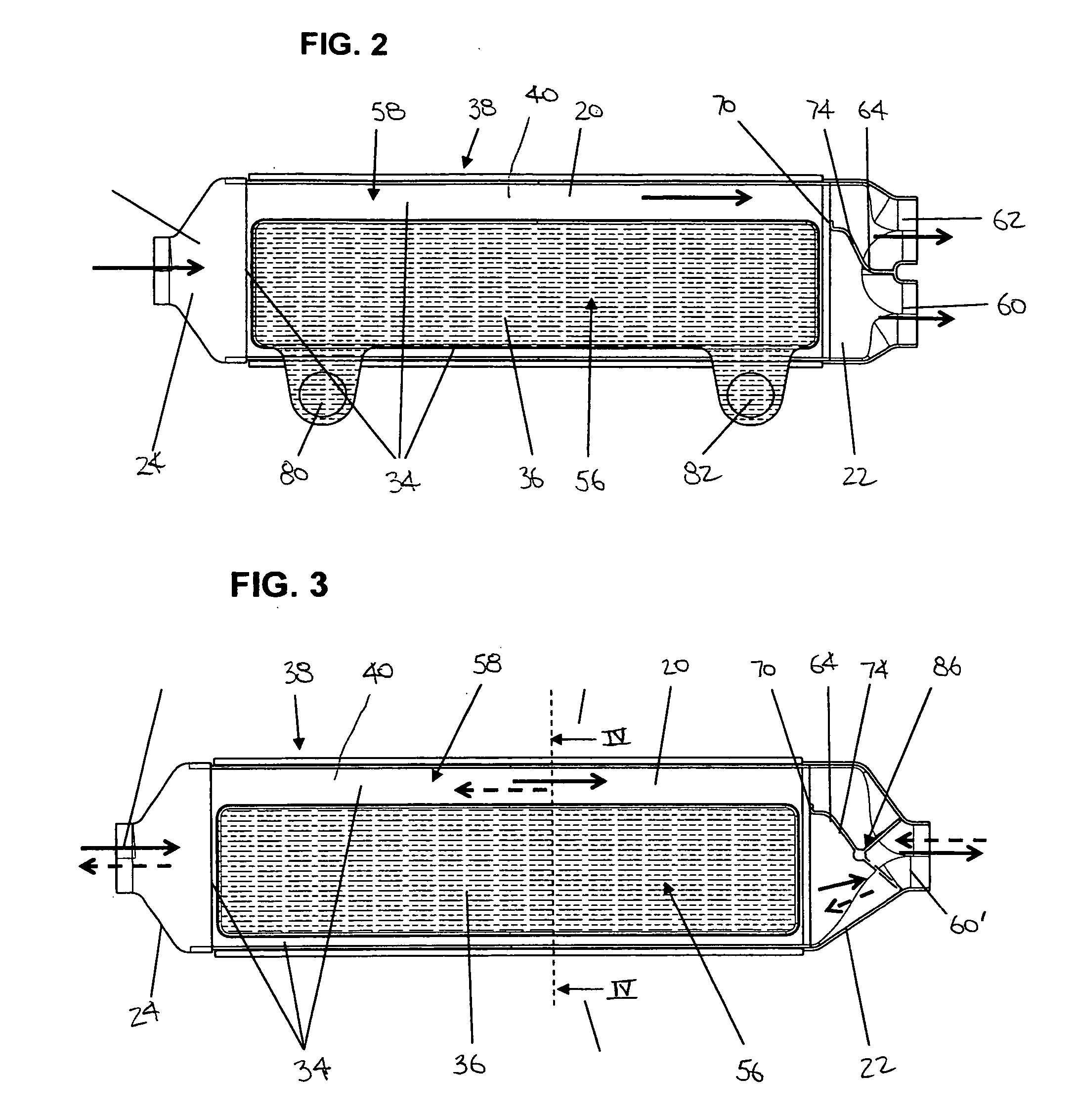
[0025] A perspective, partially cut-away view of part of the heat exchanger according to the invention is depicted in FIG. 1 for use in cooling gas such as exhaust or charge air. The heat exchanger may be incorporated in a suitable fashion, for example, in an exhaust gas recirculation system (not shown). In the practical example illustrated in FIG. 1, only two flat tubes 20 are stacked one on the other and each provided with collecting tanks 22, 24 on the ends of the heat exchanger (see FIG. 2). It should, of course, be understood that although only two flat tubes are shown in the Figures, more than two flat tubes 20 can be used in the scope of the present invention depending, for example, on the heat exchange requirements of the system with which it may be used.

[0026] The flat tubes 20 may be advantageously assembled from two identically shaped plates 26, 28, with one of the plates 26 or 28 then rotated 180° around the longitudinal axis relative to the other. The plates 26, 28 may...


PUM


Abstract

A heat exchanger including flat tubes having cooling passages for a gas and a bypass for the gas separate from the cooling passages, and coolant channels defined between every two flat tubes adjacent the tube passages and spaced from the bypass of the tubes. The tubes define a cooled area adjacent the passages and an uncooled area adjacent the bypass substantially spaced from the channels.

Description

CROSS REFERENCE TO RELATED APPLICATION(S) [0001] Not applicable. STATEMENT REGARDING FEDERALLY SPONSORED RESEARCH OR DEVELOPMENT [0002] Not applicable. REFERENCE TO A MICROFICHE APPENDIX [0003] Not applicable. TECHNICAL FIELD [0004] The present invention relates to a heat exchanger and more particularly to a heat exchanger in which gas may be selectively cooled or not cooled by a coolant. BACKGROUND OF THE INVENTION AND TECHNICAL PROBLEMS POSED BY THE PRIOR ART [0005] Heat exchangers used with recirculating exhaust gas are highly advantageous in that they reduce emissions in vehicles. Recycled exhaust must be cooled in order to achieve high efficiency during recirculation, especially to achieve better degrees of filling. However, it will be appreciated by those skilled in the art that the entire system (vehicle with internal combustion engine) and an overall energy balance are at issue. Toward that end, all operating phases in vehicles have heretofore been analyzed to account for al...

Claims


Application Information

Patent Timeline
Patent Type & Authority Applications(United States)
IPC IPC(8): F28F27/02F28D7/16F28D9/00
CPCF02M25/0703F02M25/0729F02M25/0737F02M25/0777F28D7/1684F28D9/0037Y10S165/11F28D21/0003F28D2021/0082F28F27/02F28F2250/06Y02T10/121F28D9/0043F28F2250/104F02M26/12F02M26/26F02M26/32F02M26/57
Inventor BROST, VIKTORRUF, CHRISTOPH
Owner MODINE MFG CO
Why Eureka
Try Eureka