
Device pairing

a technology of devices and pairing, applied in the field of devices pairing, can solve the problems of poor video quality, inability to use, impracticality, if not unusability, etc., and achieve the effect of further enhancing security

Inactive Publication Date: 2006-02-16
THOMSON LICENSING SA
View PDF20 Cites 37 Cited by
  • Summary
  • Abstract
  • Description
  • Claims
  • Application Information

AI Technical Summary

Benefits of technology

[0012] The security module is thus able to provide the device state and, as the device state can change, the usage flexibility is improved.
[0018] The method provides an easy way of providing a device with a device state.
[0025] In a further preferred embodiment, security is further enhanced, if desired by running at least one challenge-response protocol, requiring every protocol to succeed before pairing the devices.

Problems solved by technology

Unfortunately, the video quality is bad and it is only possible to watch one and the same program on all the connected TV sets.
While other, more complex solutions exist, it will be appreciated that even this relatively simple solution implicates big modifications of the CA system and a strong linking with the broadcaster's back office, and that it is, for these reasons, impractical, if not unusable, in a horizontal market.
Although this method could be used to pair decoders, it would mean that a master decoder and a slave decoder are differentiated, which is a problem for the manufacturer, the retailer, and the after-sales staff.
This method as well is limited in some situations in that there is a certain lack of flexibility, since for example a slave decoder must be paired with a particular master for it to work.
As before, this is a problem for the manufacturer, the retailer, and the after-sales staff.

Method used


Image

  • Device pairing
  • Device pairing
  • Device pairing

Examples


Embodiment Construction

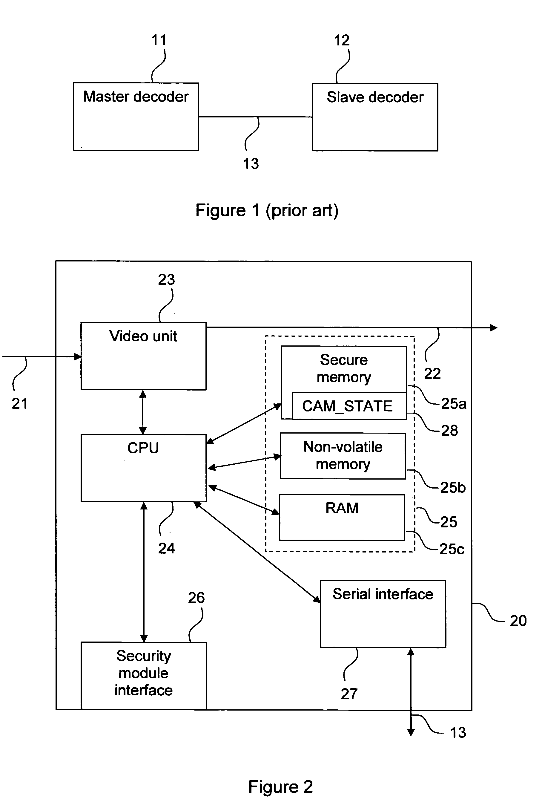
[0036]FIG. 2 is a simplified illustration of the architecture of a preferred embodiment of a decoder 20 according to the invention. The decoder 20 comprises a Central Processing Unit (CPU) 24, a video unit 23, a security module interface 26 advantageously in the form of a ISO-7816 compliant smart card interface, a serial interface 27, and memory 25, advantageously in the form of a secure, non-volatile memory 25a, a non-volatile memory25b, and a Random Access Memory (RAM) 25c. The video unit 23 receives the video stream through an incoming connection 21, extracts Entitlement Control Messages (ECMs) and Entitlement Management Messages (EMMs), and passes them to the CPU 24 to be forwarded via the security module interface 26 to the security module (not shown in this figure). The video unit 23, if authorised by the security module, also descrambles the video stream and outputs it on connection 22, normally connected to a display (not shown). The security module interface 26 realises the...


PUM


Abstract

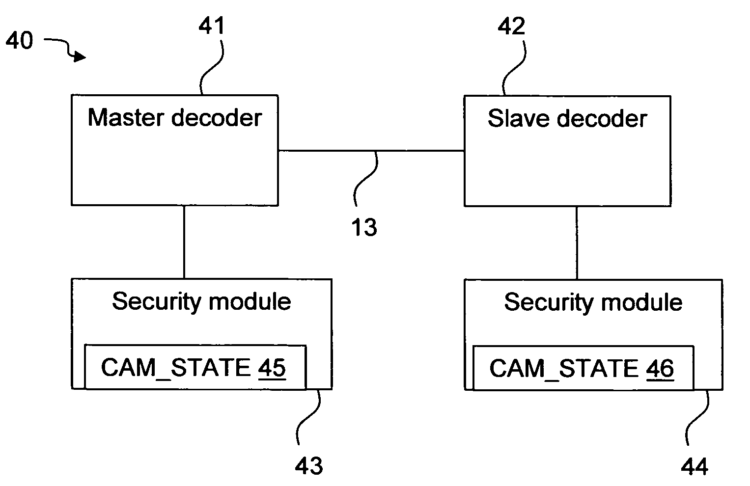
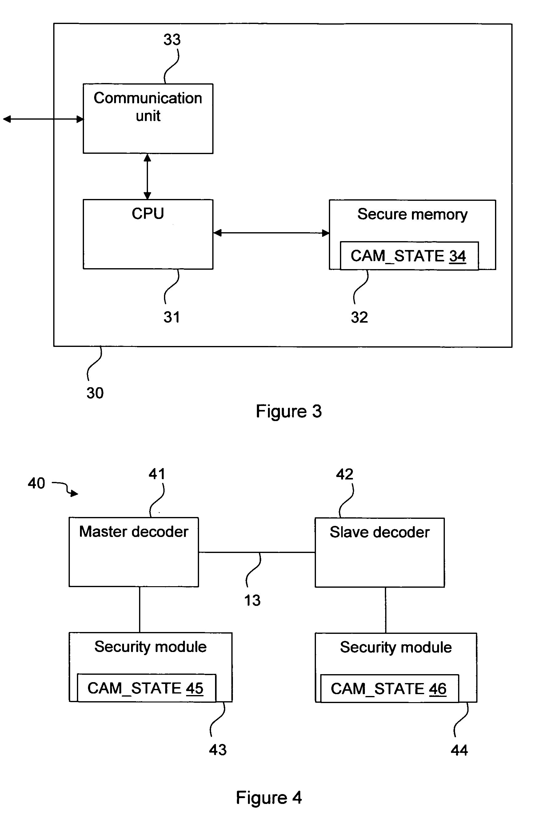
The invention relates to pairing a slave device with a master device, for example decoders in a conditional access system. There is provided a security module that stores a device state that indicates whether a decoder shall be a master or a slave decoder. There is also provided a method in a conditional access system of providing a device with a device state stored on a security module. It is detected that the security module is in connection with the device and the device state is transferred from the security module to the device. There is further provided a method of pairing a slave device with a master device. The slave device asks the master device to identify itself, the master device returns an identification, and if the slave device has not yet been paired with a master device, it checks the identity of the master device and, if the identity is verified pairs with the master device. There is also provided a first, slave, device for pairing with a second, master, device. The first device comprises an interface for sending an identification command to and receiving an identification message from the master device, and a processor for checking the identity of the second device and pairing the first device with the second device.

Description

FIELD OF THE INVENTION [0001] The present invention relates generally to pairing of devices, and in particular to pairing of devices in systems in which terminals are given conditional access to content. The present invention is advantageously applied to pairing of decoders in Pay TV systems. BACKGROUND OF THE INVENTION [0002] The term “decoder,” which will be used as an exemplary implementation of a terminal, as used herein may refer to a decoder physically separate from a receiver, a combined receiver and decoder, such as in a set-top box (decoder), or a decoder having additional functions, for example recording devices, displays or web browsers. It will also be assumed that the general concepts of conditional access systems are well known and that they, as such, will not need to be described further hereinafter where this is not needed for the comprehension of the invention. [0003] Conditional access systems, such as Pay TV that will be used throughout the description, has gained...

Claims


Application Information

Patent Timeline
Patent Type & Authority Applications(United States)
IPC IPC(8): H04N11/00G06F21/62H04N7/16
CPCH04N7/163H04N21/4623H04N21/44227H04N21/43615H04N21/6334
Inventor DIEHL, ERICANDREAUX, JEAN-PIERRECARBONNEL, LOUIS-XAVIERDURAND, ALAIN
Owner THOMSON LICENSING SA
Learn More