
Communication terminal and method of establishing communication

a communication terminal and communication terminal technology, applied in the direction of transmission monitoring, generating/distributing signals, broadcasting service distribution, etc., can solve the problems of inconvenient search operation and significant power consumption for users, and achieve the effect of saving power consumption and efficient notifying another nearby

Active Publication Date: 2006-02-16
SONY COMPUTER ENTERTAINMENT INC
View PDF4 Cites 71 Cited by
  • Summary
  • Abstract
  • Description
  • Claims
  • Application Information

AI Technical Summary

Benefits of technology

[0007] Accordingly, an object of the present invention is to provide a technology capable of searching for another communication terminal automatically and efficiently notifying another nearby communication terminal of its own presence, and also to provide a technology for saving power consumed in this process.
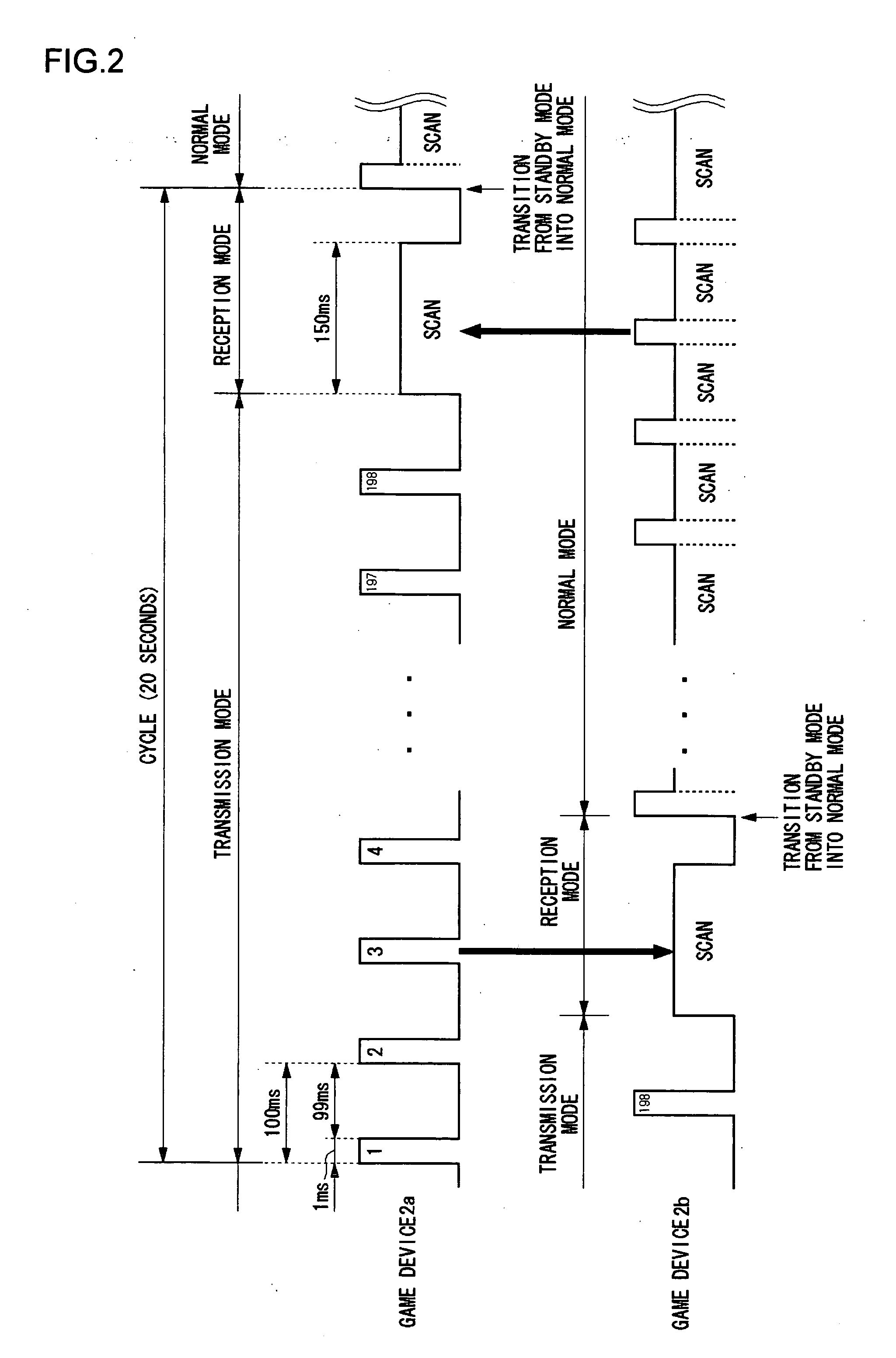
[0008] In order to achieve the aforementioned objects, the present invention provides a communication terminal comprising: a transmission control unit which controls a transmission mode in which a broadcast signal is transmitted a plurality of times; and a reception control unit which controls a reception mode in which the broadcast signal transmitted from another communication terminal is monitored, wherein the transmission control unit and the reception control unit execute the transmission mode and the reception mode alternately. The transmission control unit and the reception control unit execute the transmission mode and the reception mode alternately. With this, a communication terminal is capable of notifying another communication terminal of its own presence and is capable of searching for another communication terminal, without requiring the user's attention.

Problems solved by technology

When scanning is performed continuously in a situation where it is uncertain whether the other communication terminal is within the communication range, significant power is consumed.
However, the operation for a search is inconvenient for users.

Method used


Image

  • Communication terminal and method of establishing communication
  • Communication terminal and method of establishing communication
  • Communication terminal and method of establishing communication

Examples


Embodiment Construction

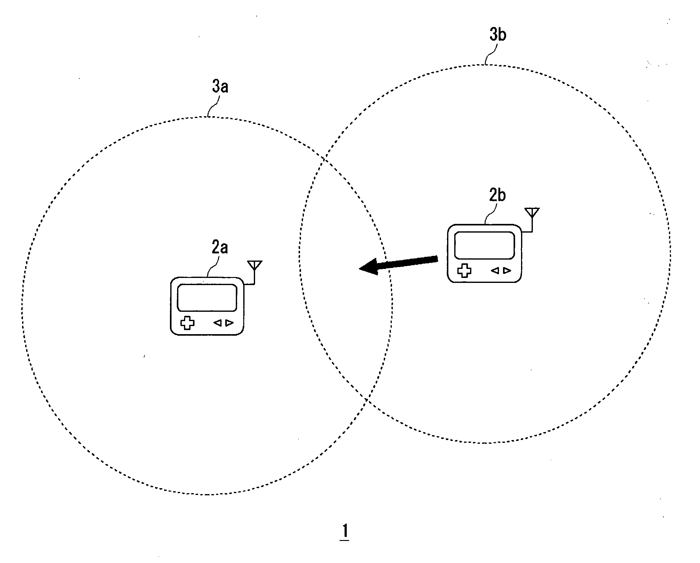
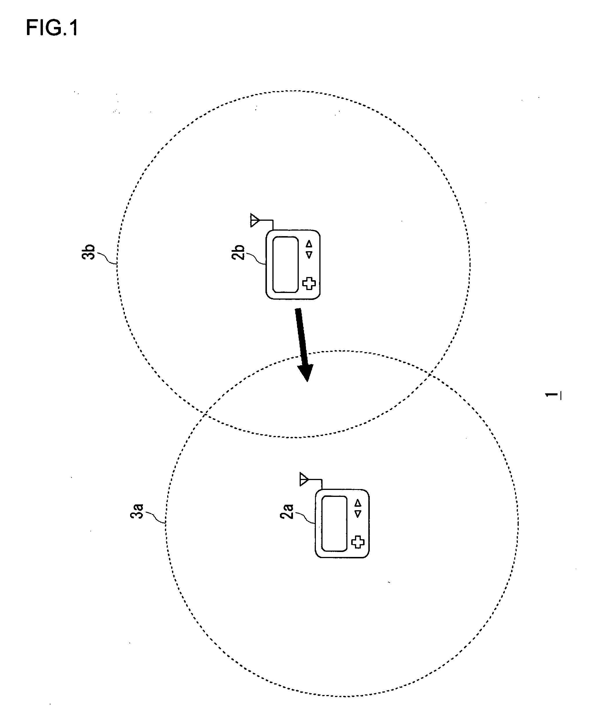
[0014]FIG. 1 illustrates a communication system 1 according to an example of the present invention. The communication system 1 is comprised of a plurality of wireless communication terminal (hereinafter, simply referred to as “communication terminals”). In FIG. 1, two portable game devices 2a and 2b (generically referred to as game devices 2 as required) are illustrated as examples of the communication terminals. The number of game devices 2 is not limited to two. Three or more devices may be provided. Each of the game devices 2 is provided with a wireless communication function. By bringing a plurality of game devices 2 together, a wireless network is built. A wireless ad hoc network is built by using a wireless LAN standard such as IEEE802.11b.

[0015] The game device 2a has a communication range 3a and the game device 2b has a communication range 3b. It will be assumed that the communication range 3a is identical in size with the communication range 3b. In the illustrated state, t...


PUM


Abstract

A communication terminal is provided with a transmission control unit for controlling a transmission mode in which a broadcast signal is transmitted a plurality of times, and a reception control unit for controlling a reception mode in which the broadcast signal transmitted from another communication terminal is monitored. The transmission control unit and the reception control unit execute the transmission mode and the reception mode cyclically and alternately. To achieve power saving, time reserved for execution of the transmission mode in a cycle is set to be longer than time reserved for execution of the reception mode in the cycle.

Description

BACKGROUND OF THE INVENTION [0001] 1. Field of the Invention [0002] The present invention relates to a technology for establishing communication with another communication terminal. [0003] 2. Description of the Related Art [0004] With the realization of miniaturization and lightweight of information terminals, it has become common nowadays for people to carry an information terminal. In association with this, study has been vigorously undertaken on the construction of wireless ad hoc network for on-demand communication. In an ad hoc network, base stations and access points are not necessary. It is therefore easy to build a network even in places where no such infrastructure exists. By using an ad hoc network, a plurality of users may enjoy a game together without being constrained in place, as they join each other, bringing their own portable game devices and communicating wirelessly. [0005] An ad hoc network is built by allowing terminals to communicate with each other using techno...

Claims


Application Information

Patent Timeline
IPC IPC(8): H04J3/26A63F13/31A63F13/327G06F1/04H04B17/382H04W24/00H04W52/02H04W84/10H04W84/12H04W88/02
CPCH04W4/06H04W8/005H04W24/00Y02B60/50H04W52/0216H04W52/50H04W76/02H04W76/10Y02D30/70H04L12/28H04W88/02
Inventor MAEKAWA, ITARUTANIGUCHI, KAZUSHIGE
Owner SONY COMPUTER ENTERTAINMENT INC
Learn More