
Method and apparatus for image forming capable of effectively recycling image forming unit

a technology of image forming and recycling, applied in the field of method and apparatus for image forming, can solve the problems of troublesome replacement operation, deterioration of obtained image and other components and devices, and the relatively long time it takes to replace the replaceable members, etc., and achieve the effect of easy replacement of replaceable image forming devices and independent replacemen

Inactive Publication Date: 2006-02-16
RICOH KK
View PDF4 Cites 25 Cited by
  • Summary
  • Abstract
  • Description
  • Claims
  • Application Information

AI Technical Summary

Benefits of technology

[0008] This patent specification describes a novel image forming apparatus which allows an independent and easy replacement of replaceable image forming devices. In one aspect, a novel image forming apparatus includes an image forming unit detachably provided in the image forming apparatus. The image forming unit include a housing, a plurality of replaceable devices, and a nonvolatile memory. The plurality of replaceable devices are replaceably mounted inside the housing. The nonvolatile memory is mounted on the housing and stores lifetime information of the image forming unit and each one of the plurality of replaceable devices.

Problems solved by technology

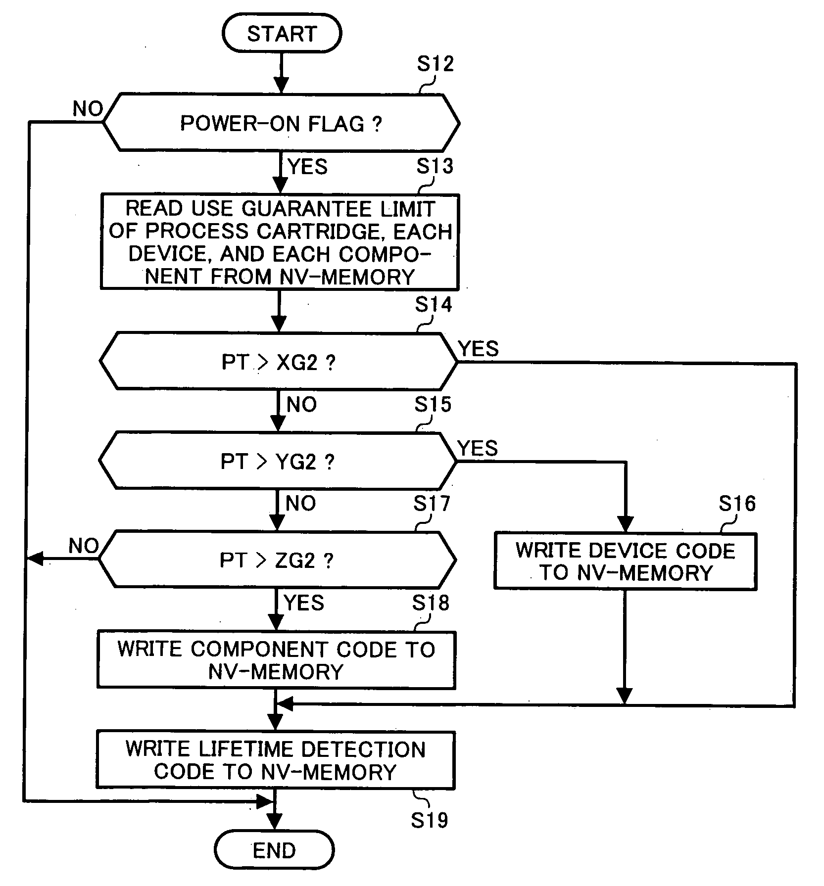
However, in the background process cartridge, when the photoconductor is detected to be worn out to the end of its lifetime and replaced with a new one, such components as a charging device and a cleaning device attached around the photoconductor need to be detached from a housing of the process cartridge, even though the components are not yet at the end of lifetime thereof.
Therefore, it takes a relatively long time to replace the replaceable members, and a replacement operation is troublesome.
As a result, an obtained image and other components and devices may be deteriorated due to the end of lifetime of the replaceable members.

Method used


Image

  • Method and apparatus for image forming capable of effectively recycling image forming unit
  • Method and apparatus for image forming capable of effectively recycling image forming unit
  • Method and apparatus for image forming capable of effectively recycling image forming unit

Examples


Embodiment Construction

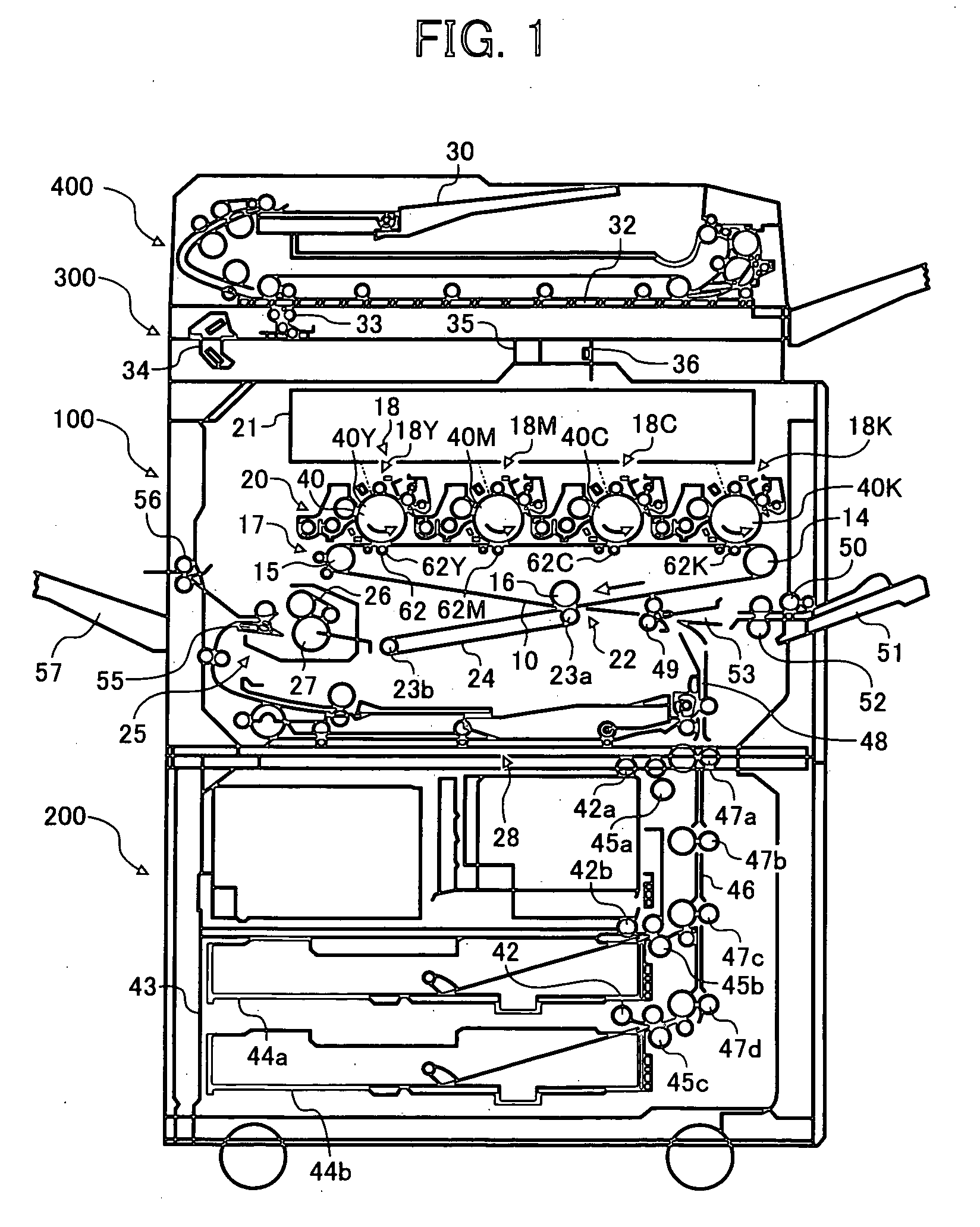
[0037] In describing the embodiments illustrated in the drawings, specific terminology is employed for the purpose of clarity. However, the disclosure of this patent specification is not intended to be limited to the specific terminology so used, and it is to be understood that substitutions for each specific element can include any technical equivalents that operate in a similar manner. Referring now to the drawings, wherein like reference numerals designate identical or corresponding parts throughout the several views, particularly to FIG. 1, an image forming apparatus 100 according to an embodiment of the present invention is described.

[0038]FIG. 1 is a schematic view illustrating a configuration of the image forming apparatus 100, which is a tandem-type color copier using an indirect transfer method. The image forming apparatus 100 is placed on a sheet-feeding table 200. A scanner 300 and an ADF (automatic document feeder) 400 are placed on the image forming apparatus 100.

[003...


PUM


Abstract

An image forming apparatus which allows an independent and easy replacement of replaceable image forming devices includes an image forming unit detachably provided in the image forming apparatus. The image forming unit include a housing, a plurality of replaceable devices, and a nonvolatile memory. The plurality of replaceable devices are replaceably mounted inside the housing. The nonvolatile memory is mounted on the housing and stores lifetime information of the image forming unit and each one of the plurality of replaceable devices.

Description

CROSS REFERENCE TO RELATED APPLLICATION [0001] This application claims priority to Japanese patent application no. 2004-236740 filed on Aug. 16, 2004, the disclosure of which is incorporated by reference herein in its entirety. BACKGROUND OF THE INVENTION [0002] 1. Field of the Invention [0003] The present invention relates to a method and apparatus for image forming, and more particularly to a method and apparatus for image forming capable of effectively recycling an image forming unit. [0004] 2. Discussion of the Background Arts [0005] In a background image forming apparatus, a toner cartridge or a process cartridge is detachably provided in the background image forming apparatus as an image forming unit, and includes a nonvolatile memory which stores lifetime information of the toner cartridge such as guarantee information and operation information of the toner cartridge. In the background image forming apparatus, the nonvolatile memory stores the guarantee information of the pro...

Claims


Application Information

Patent Timeline
IPC IPC(8): G03G15/00G03G15/08G03G21/00
CPCG03G2215/00987G03G21/1889
Inventor KIKUCHI, HIDEOISOBE, TAKUNDO
Owner RICOH KK
Learn More