Injection port and method of making the same

a technology of injection port and tube, which is applied in the field of injection port and method of making the same, can solve the problems of prone to damage of shrink wrap and potential leakage between the external surface of the plug and the mating surface of the tube,

Inactive Publication Date: 2006-02-16
WEST PHARM SERVICES INC
View PDF18 Cites 35 Cited by
  • Summary
  • Abstract
  • Description
  • Claims
  • Application Information

AI Technical Summary

Problems solved by technology

However, the shrink wrap is prone to damage because it is exposed on an external surface of the injection port and may potentially permit the plug to release from the tube.
In addition, because the plug is inserted into the tube following molding and curing, leaks may potentially form between the external surface of the plug and a mating surface of the tube.

Method used


Image

  • Injection port and method of making the same
  • Injection port and method of making the same
  • Injection port and method of making the same

Examples


Embodiment Construction

[0018] Certain terminology is used in the following description for convenience only and is not limiting. The words “right”, “left”, “lower” and “upper” designate directions in the drawings to which reference is made. The words “inwardly” and “outwardly” refer to directions toward and away from, respectively, the geometric center of the preferred embodiments of the injection port and designated parts thereof. The terminology includes the above-listed words, derivatives thereof and words of similar import. Additionally, the word “a” as used in the specification means “at least one”.

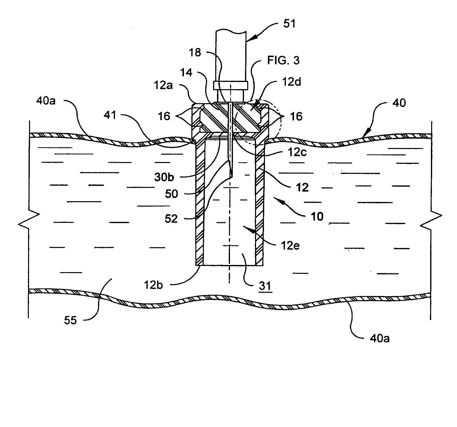
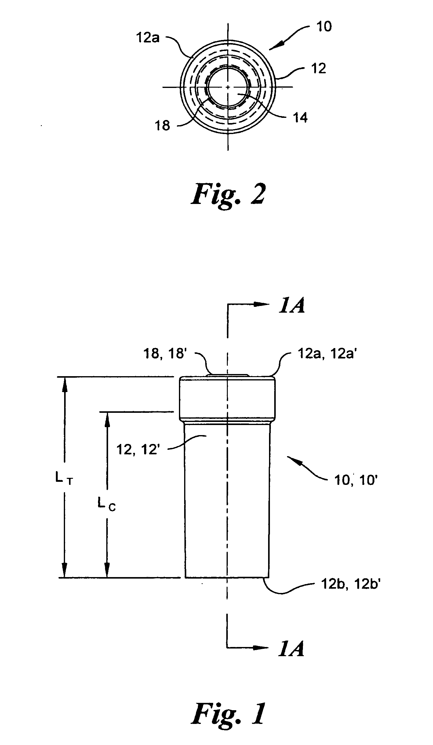
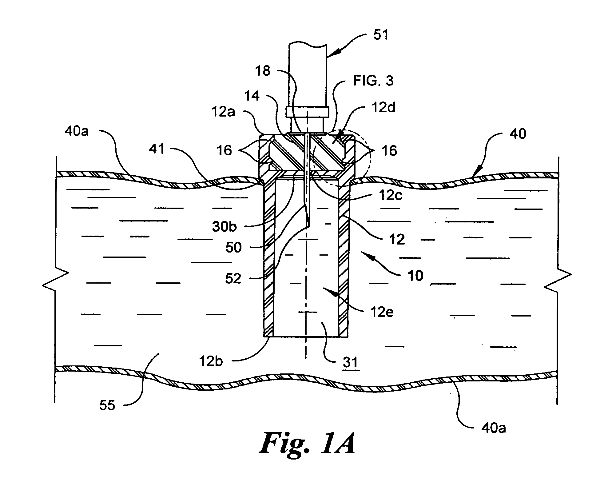
[0019] Referring to FIGS. 1-3, a first preferred embodiment an injection port, generally designated 10, includes a generally hollow tube 12 and a polymeric plug 14. The tube 12 is preferably constructed of an injection molded polyvinyl chloride (“PVC”) material and the plug 14 is preferably constructed of a thermoplastic elastomer (“TPE”) material. The PVC material of the tube 12 is preferred for its form...


PUM

PropertyMeasurementUnit
thermoplastic elastomeraaaaaaaaaa
hardnessaaaaaaaaaa
compression setaaaaaaaaaa

Abstract

An injection port for an intravenous bag including a generally hollow tube that is mountable to the intravenous bag. The hollow tube has a first end. A polymeric plug is mounted in the first end. The polymeric plug is integrally molded into the tube proximate the first end. A method for constructing the injection port including injecting a first molding material into a mold cavity, allowing the first molding material to at least partially cure and harden, moving a movable mold part to expose a first cavity defined by inner surfaces of the at least partially cured and hardened molding material, injecting a second mold material into the first cavity, allowing the second molding material to at least partially cure and harden such that the second molding material bonds with the inner surfaces and removing the injection port from the mold.

Description

CROSS-REFERENCE TO RELATED APPLICATIONS [0001] This application claims the benefit of U.S. Provisional Patent Application No. 60 / 575,020, filed May 27, 2004.BACKGROUND OF THE INVENTION [0002] Intravenous (“IV”) bags typically include an injection port mounted to one of the walls of the bag that is used as a point of entry to inject medication or other liquids into the IV bag. The injection port is typically constructed of an injection molded, hollow polyvinyl chloride (“PVC”) tube with an elastomeric plug mounted to one end of the hollow PVC tube. The plug is mounted at an end of the hollow PVC tube by a shrink band that engages the plug and the hollow tube to hold the plug in position relative to the tube. The PVC tube is mounted to the IV bag such that the plug is facing out of the IV bag. [0003] The typical injection port is constructed by molding the PVC tube, separately molding the plug and placing the plug onto a first end of the hollow PVC tube. The shrink band is then positi...

Claims


Application Information

Patent Timeline
Patent Type & Authority Applications(United States)
IPC IPC(8): B29C45/14B28B7/22A61J1/05A61J1/10B29C45/16
CPCA61J1/10B29C45/1615B29C45/1635B29L2031/7148B29K2027/06B29K2221/003B29L2031/565B29C45/1676
Inventor CONARD, WILLIAM A.BUCK, ROBERTSTRAUSBAUGH, NEILKING, ROBERT J.CRAMMER, DIANE M.
Owner WEST PHARM SERVICES INC
Why Eureka
Try Eureka