Test apparatus and test method

a testing device and test method technology, applied in the field of testing devices and testing, can solve the problems of not being able to detect the matching or mismatch between the output patterns, the device under test may not define the timing in which the output of the output pattern sequence is started, and the testing device may fail to detect the output pattern sequence identical with the header pattern sequence, etc., to achieve the effect of easy pursuit of the caus

Active Publication Date: 2006-02-16
ADVANTEST CORP
View PDF3 Cites 21 Cited by
  • Summary
  • Abstract
  • Description
  • Claims
  • Application Information

AI Technical Summary

Benefits of technology

[0039] According to the present invention, it is possible to adequately test a margin of an output signal output from a device under test. Moreover, although the output timing of the output pattern sequence is not defined, it is possible to synchronize and compare the output pattern sequence with reading the expectation pattern sequence. Furthermore, it is possible to easily pursue a cause thereof when a header pattern showing the start of the test has not been detected. Moreover, it is possible to adequately set a range validating the detection of header pattern sequence.

Problems solved by technology

However, when changing these parameters, the head pattern cannot be acquired justly, and thus it is not possible to detect match or mismatch between the output pattern and the expectation pattern.
Moreover, some devices under test may not define the timing in which the output of the output pattern sequence is started.
However, the testing device may fail in detecting the output pattern sequence identical with the header pattern sequence on account of failures of the device under test.
In this case, it was difficult to analyze a cause failed in detecting the header pattern sequence conventionally.
However, in case where the testing device fails in detecting the header pattern sequence outside the range of the comparison window, it may be difficult to perform failure analysis due to the mixture of unnecessary data outside the testing object range and the comparison result of the testing object when information showing the detection failure is recorded in an error log or the like or is informed a user.

Method used


Image

  • Test apparatus and test method
  • Test apparatus and test method
  • Test apparatus and test method

Examples


example 1

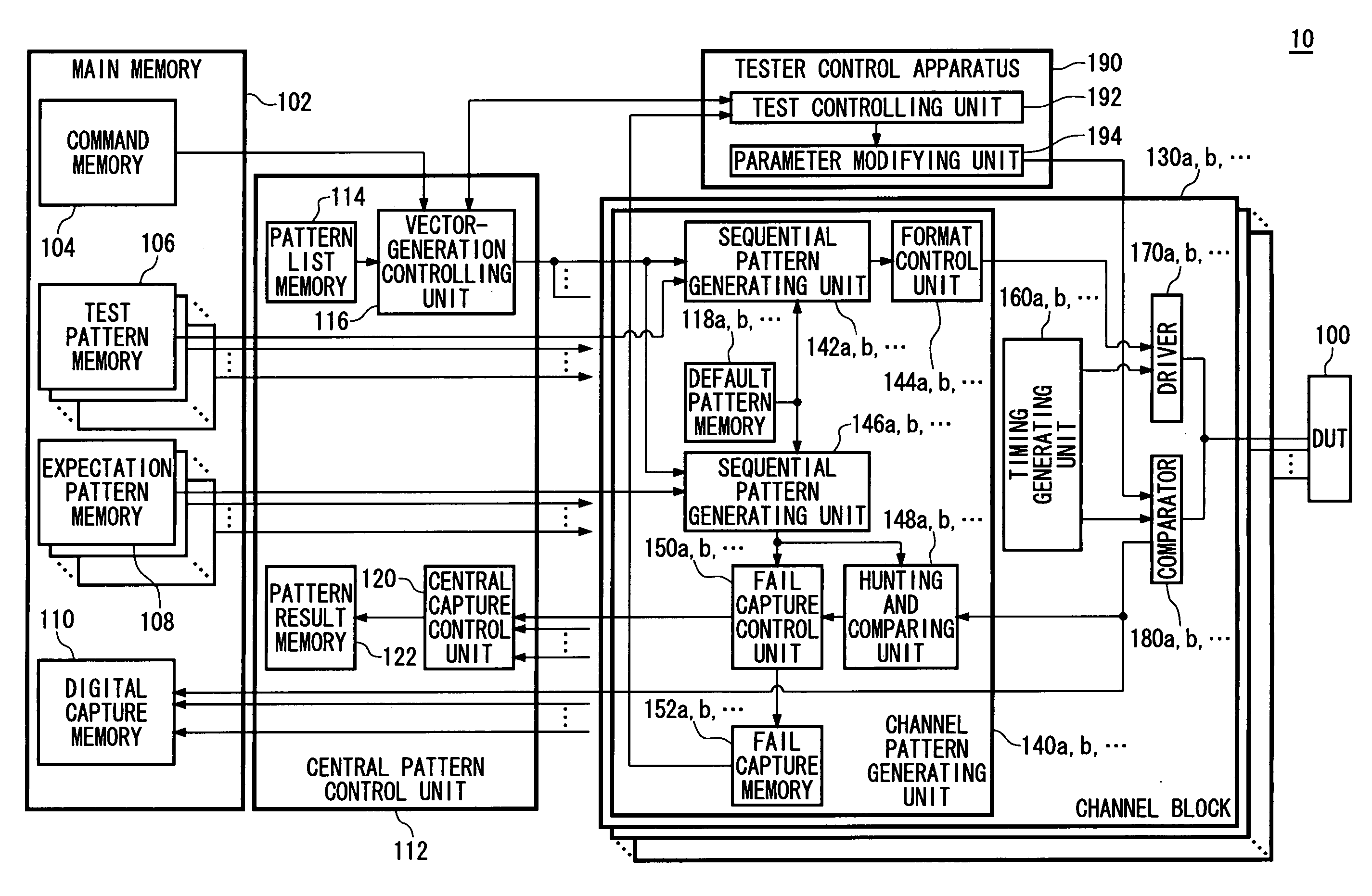
[0058]FIG. 1 shows a configuration of a testing device 10 according to Example 1. The testing device 10 is a testing device that tests a device under test (DUT) 100 including one terminal or a plurality of terminals, and has a margin testing function to test a margin of an output signal output from the output terminal of the device under test. The testing device 10 includes a main memory 102, a central pattern control unit 112, a plurality of channel blocks 130, and a tester control device 190.

[0059] The main memory 102 stores a test program for the DUT 100, and records an output pattern output from the DUT 100 by executing the test program. The main memory 102 has a command memory 104, a plurality of test pattern memories 106, a plurality of expectation pattern memories 108, and a digital capture memory 110.

[0060] The command memory 104 stores each command included in the test program. Each of the plurality of test pattern memories 106 is provided corresponding to each terminal o...

example 2

[0105]FIG. 7 shows a configuration of the testing device 10 according to Example 2. The testing device 10 according to the present example may not include the default pattern memory 118 in the testing device 10 shown in FIG. 1. Since the components of FIG. 7 having the same reference numbers as those of FIG. 1 have the generally same functions or configurations as those of FIG. 1, their descriptions will be omitted except for the following difference. Moreover, since the channel blocks 130a, 130b, . . . shown in FIG. 1 have the generally same functions as one another in the present example, these blocks are generally referred to as a channel block 130.

[0106]FIG. 8 shows a configuration of the hunting and comparing unit 148 according to Example 2. The hunting and comparing unit 148 has a header pattern storing unit 600, a header pattern detecting unit 610, an alignment unit 620, an expectation comparing unit 630, a timing adjusting unit 640, a selector 650, and en error informing un...

example 3

[0121]FIG. 10 shows a configuration of the testing device 10 according to Example 3. The testing device 10 according to the present example may not include the default pattern memory 118 in the testing device 10 shown in FIG. 1. Since the components of FIG. 10 having the same reference numbers as those of FIG. 1 have the generally same functions or configurations as those of FIG. 1, their descriptions will be omitted except for the following difference. Moreover, since the channel blocks 130a, 130b, . . . shown in FIG. 1 have the generally same functions as one another in the present example, these blocks are generally referred to as a channel block 130.

[0122]FIG. 11 shows a configuration of the hunting and comparing unit 148 according to Example 3. The hunting and comparing unit 148 has a header pattern detecting unit 700, an alignment unit 710, an expectation comparing unit 720, and a selection writing unit 730. The header pattern detecting unit 700 inputs an output pattern seque...


PUM


Abstract

There is provided a testing device including: a first signal comparator operable to acquire a value of an output pattern based on a result that is obtained by comparing a voltage of an output signal and a first threshold value voltage in a first strobe timing, in order to acquire a first output pattern sequence; a second signal comparator operable to acquire a value of an output pattern based on a result that is obtained by comparing a voltage of an output signal and a second threshold value voltage in a second strobe timing, in order to acquire a second output pattern sequence; a header pattern sequence detecting unit operable to detect that the first output pattern sequence is identical with a header pattern sequence; and an expectation comparing unit operable to output a comparison result between the second output pattern sequence acquired by the second signal comparator and an expectation pattern sequence when detecting a correspondence between the first output pattern sequence and the header pattern sequence.

Description

CROSS REFERENCE TO THE RELATED APPLICATION [0001] The present application is a continuation application of PCT / JP2005 / 010829 filed on Jun. 14, 2005, which claims priority from Japanese Patent applications 2004-179857 filed on Jun. 17, 2004, 2004-192195 filed on Jun. 29, 2004, 2004-183067 filed on Jun. 21, 2004, and 2004-212234 filed on Jul. 20, 2004, the entire contents of which are incorporated herein by reference for all purposes.BACKGROUND OF THE INVENTION [0002] 1. Field of the Invention [0003] The present invention relates to a testing device and a testing method deciding the good or bad of an electronic device by comparing an output pattern of a signal output from the electronic device and a predetermined expectation pattern. [0004] 2. Description of Related Art [0005] A testing device tests a device under test (DUT) that is an object of test based on a test program. The test program includes commands to be executed by the testing device and an expectation pattern to be compar...

Claims


Application Information

Patent Timeline
Patent Type & Authority Applications(United States)
IPC IPC(8): G06F19/00G01R31/30G01R31/319G01R31/3193
CPCG01R31/319G01R31/31937G01R31/31932G01R31/31922G01R31/30
Inventor OZORA, SATOSHINAKAGAWA, TETSUROTSUNODA, MAKOTOTAKAIWA, NOBUMASA
Owner ADVANTEST CORP
Why Eureka
Try Eureka