
Rotary type component force measuring device

a technology of component force and measuring device, which is applied in the direction of force measurement, force/torque/work measurement apparatus, instruments, etc., can solve the problems of difficult to correct each component of the component force, and large interference to become detection error factor, etc., to achieve highly accurate component force and reduce the detection error of strain gauge.

Inactive Publication Date: 2006-02-23
A&D CO LTD
View PDF3 Cites 82 Cited by
  • Summary
  • Abstract
  • Description
  • Claims
  • Application Information

AI Technical Summary

Benefits of technology

[0011] The present invention has been made in view of the conventional problems as described above, and an objective of the invention is to provide an rotary type component force measuring device, which can reduce a detection error of the strain gauge and can find a correct and highly accurate component force.
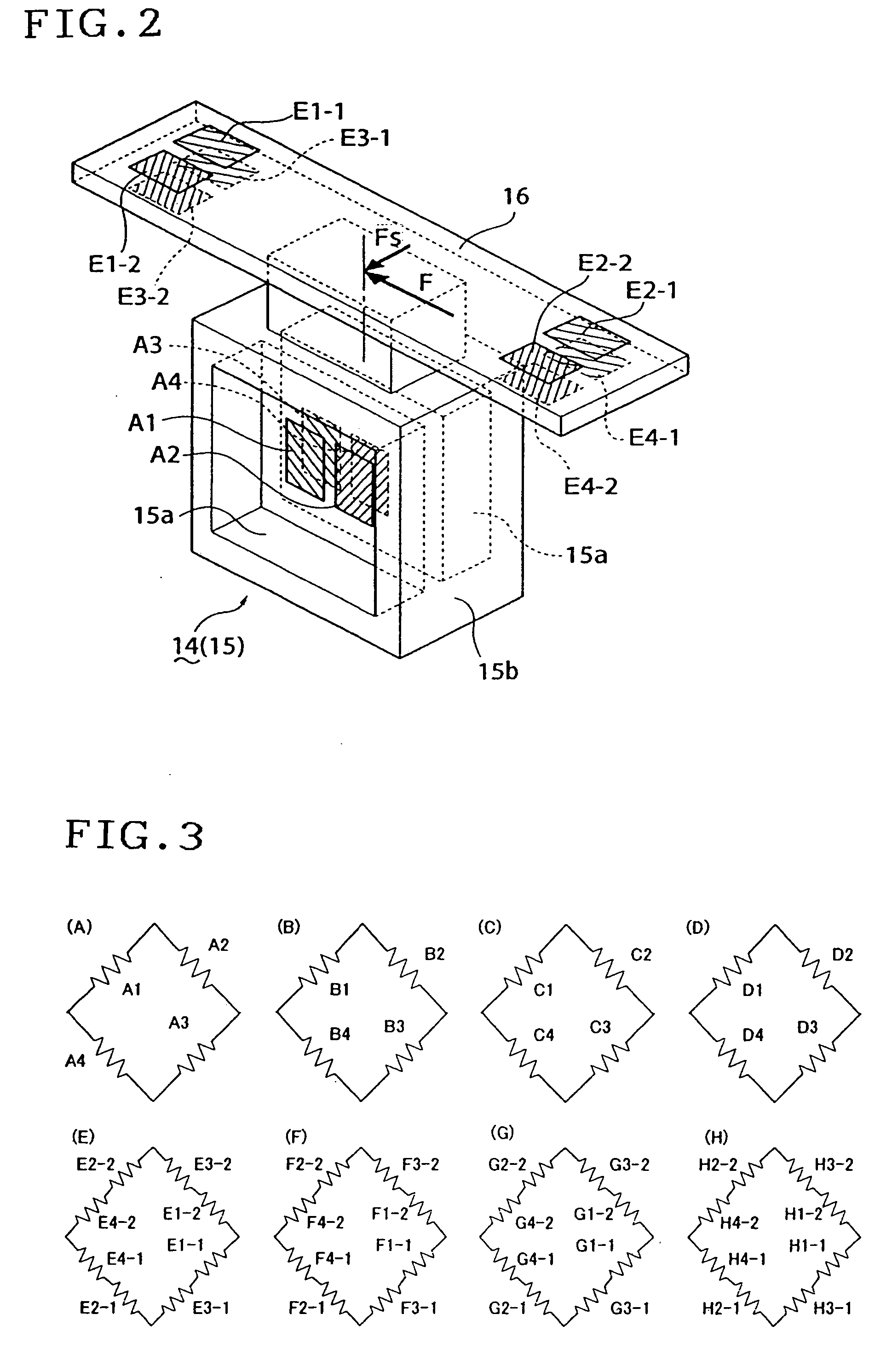
[0019] Since the character I shaped sectional shear beam type is adapted in this manner, comparing to an arm having a square type section, the effect of a shearing component due to the side force Fs applied on the sensitive surface can be reduced, and a highly accurate output signal can be obtained from the shear gauge.
[0021] Thus, according to the rotary type component force measuring device of the present information, since eight output signals are simultaneously sampled for every rotation angle, a quantization error of the rotation angle is controlled, and at the same time, the output signals of all rotation angles can be obtained at a high speed, so that the errors of the output signals and the six component forces are reduced, and correctly high accurate component forces can be found for every rotation angle.
[0023] By finding the conversion matrix in advance in this manner, the conversion of a plurality of output signals into the six component forces can be quickly performed, thereby contributing to the speeding up of the signal processing.
[0026] According to the rotary type component force measuring device according to the present invention, the output signal is sampled at the wheel side according to the timing signal obtained for every receiving sensor portion, and in a state in which detection independency for every receiving sensor portion and non-interference property between different receiving sensor portions are maintained, a correction of the output signal is performed according to characteristic of strain gauge for every receiving sensor portion, and then, the output signal is coordinate-converted into six component forces, thereby realizing a high precision of the six component forces. Moreover, since the bridge circuit is constituted for every receiving sensor portion, the wiring needs not to be lengthy, and the signal error accompanied with the wiring is reduced.
[0027] Further, since the character I shaped sectional shear beam type arm is adapted, comparing to the arm having a quadrangular section, the effect of the strain component due to the side force Fs applied on the sensitive surface can be reduced, and a high accurate output signal can be obtained from the strain gauge.

Problems solved by technology

However, the multiple component force measuring device comprising such a multiple component force detector had technical problems as described below.
Hence, a force F which is an output of the strain gauge to be primarily detected has been applied with the maximum strain by a side force Fs, thereby having caused a large interference to become a detection error factor of the force F.
Further, in the multiple force component detector, the wiring of one bridge circuit has been laid across a plurality of receiving sensor portions, and the lengthening of the wiring not only has become a detection error factor of the component forces, but since errors based on strain gauge characteristics of a plurality of receiving sensor portions were added to each component of the component forces, it has been also difficult to correct each component of the component forces after the component forces were found by the bridge circuit, and no correct component forces have been found.
Moreover, to find the multiple component forces, though the component forces are found by the bridge circuit, to accomplish this, a simple addition or subtraction has been performed, and therefore, it has been necessary to dispose the receiving sensor portion by four beams, and this has been an enormous structural restraint on the multiple component force detector.
Further, if constituted by other than four beams, an extremely complicated component force detection circuit would have been required, and therefore, its realization has been difficult.

Method used


Image

  • Rotary type component force measuring device
  • Rotary type component force measuring device
  • Rotary type component force measuring device

Examples


Embodiment Construction

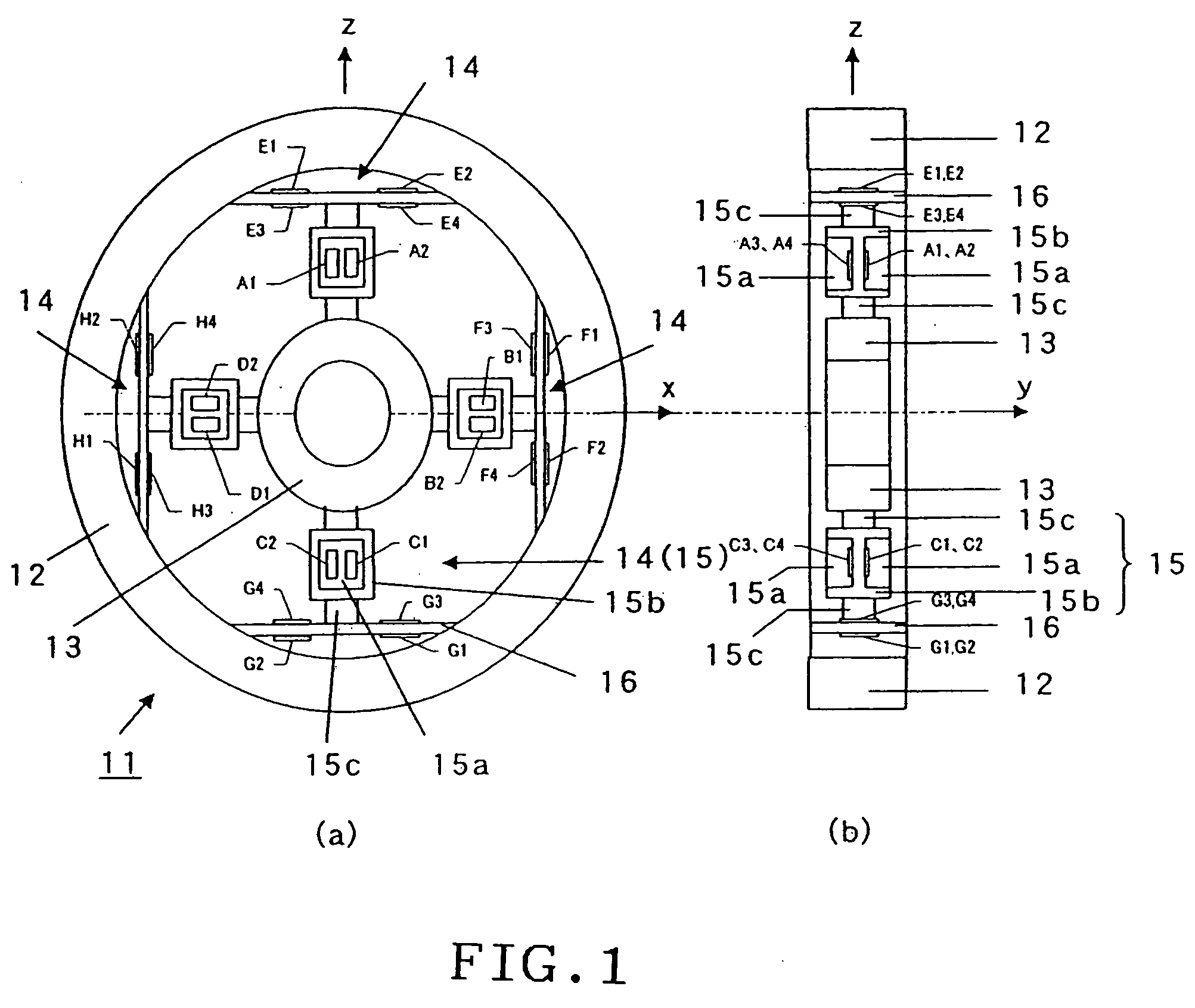
[0040] Preferred embodiments of the present invention will be described below in detail with reference to the accompanying drawings. A rotary type component force measuring device 1 of the present invention is a device which measures forces Fx, Fy, and Fz applied in the orthogonal coordinate system three directions of a wheel axle located in the center of a wheel and the orthogonal coordinate system six component forces of torques Mx, My, and Mz acting around these axes accompanied with the rotation of the wheel which is a measuring object at least by a rotary type component force detector 11 fixed to the wheel, a strain gauge disposed in the sensing beam of the rotary type component force detector 11, and a bridge circuit constituted by the gauge.

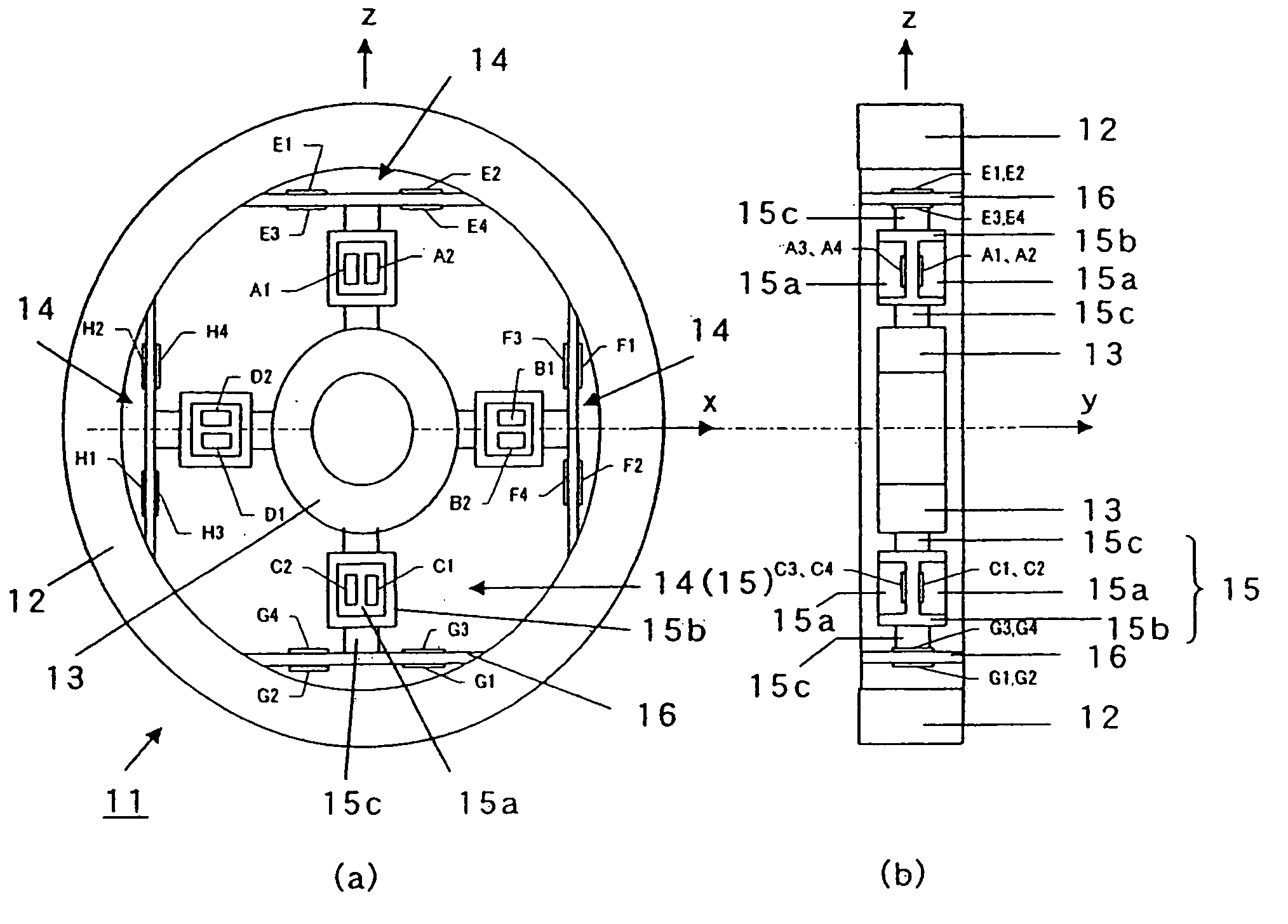
[0041]FIG. 1 is a structural illustration showing a rotary type component force detector 11 and one embodiment of the arrangement of strain gauges A1 to H4 disposed in sensing beams 15 and 16 of the rotary type component force detector 11...


PUM


Abstract

A rotary type component force measuring device capable of finding a highly accurate component force is provided. This measuring device has a rotary type component force detector comprising in integrated manner, a rim mounting frame, a hub mounting frame, a second sensing beam of a character I shaped sectional type which couples and the mounting frames, and a first sensing beam which couples the second sensing beam and the mounting frame, wherein each of front and back surfaces of receiving sensor portions adhere with each of orthogonal shearing type strain gauges A1 to H4, and a signal is derived from the strain gauges A1 to H4 by a bridge circuit for each receiving sensor portion, and the output signals from the bridge circuit are sampled by an electronic circuit disposed on the inside of a rotating unit according to the timing signal from an angle detection signal, and the output signals are transmitted to a signal processing unit disposed on the outside of the rotating unit by non-contact data transmission method, and the output signals are corrected by correction information for every rotation angle position of the detector storing the output signals beforehand, and are subjected to coordinate conversion so as to calculate the six component forces for every angle rotation.

Description

BACKGROUND OF THE INVENTION [0001] 1. Field of the Invention [0002] The present invention relates to a rotary component force measuring device for measuring six component forces of Fx, Fy, and Fz applied in axial directions x, y and z of an orthogonal coordinate system and running torques (moments) Mx, My and Mz acting around these axes. [0003] 2. Related Background Art [0004] Regarding to the techniques that involve detecting multiple component forces, there are many prior art references. For example, Japanese Patent Application Laid-Open No.05-256710 discloses a multiple component force detector which aims to obtain a detector of multiple components of force which is highly accurate with high reproducibility and simple in structure without generating interferences among components of force, thereby to reduce the manufacturing cost. Japanese Patent Application Laid-Open No.06-265423 discloses a multi component force detector which aims to provide a multi component force detector by...

Claims


Application Information

Patent Timeline
IPC IPC(8): G01L1/22G01L5/16G08C17/02G08C19/00G08C23/04
CPCG01L5/161G01L1/2237G01L5/1627
Inventor ICHIGE, TATSUO
Owner A&D CO LTD
Learn More