Method and apparatus for joining protective tape

a protective tape and tape joint technology, applied in the direction of mechanical control devices, instruments, process and machine control, etc., can solve the problems of cumbersome adjustment of the angle and height of the cutter blade, and achieve the effect of smooth and favorable cutting of the protective tap

Inactive Publication Date: 2006-02-23
NITTO DENKO CORP
View PDF3 Cites 17 Cited by
  • Summary
  • Abstract
  • Description
  • Claims
  • Application Information

AI Technical Summary

Benefits of technology

[0006] The invention has been accomplished in view of the above-mentioned circumferences. Therefore, a principal object of the invention is to provide a protective tape joining apparatus capable of promptly adjusting and setting a cutter blade at a positional posture suitable for a semiconductor wafer or a protective tape, thus smoothly and favorably cutting the protective tape in conformity with the outer shape of the semiconductor wafer.

Problems solved by technology

As a result, it is necessary to adjust the angle and height of the cutter blade with a cumbersome trouble.

Method used


Image

  • Method and apparatus for joining protective tape
  • Method and apparatus for joining protective tape
  • Method and apparatus for joining protective tape

Examples


Embodiment Construction

[0060] Description will be given below of one embodiment of the invention with reference to the attached drawings.

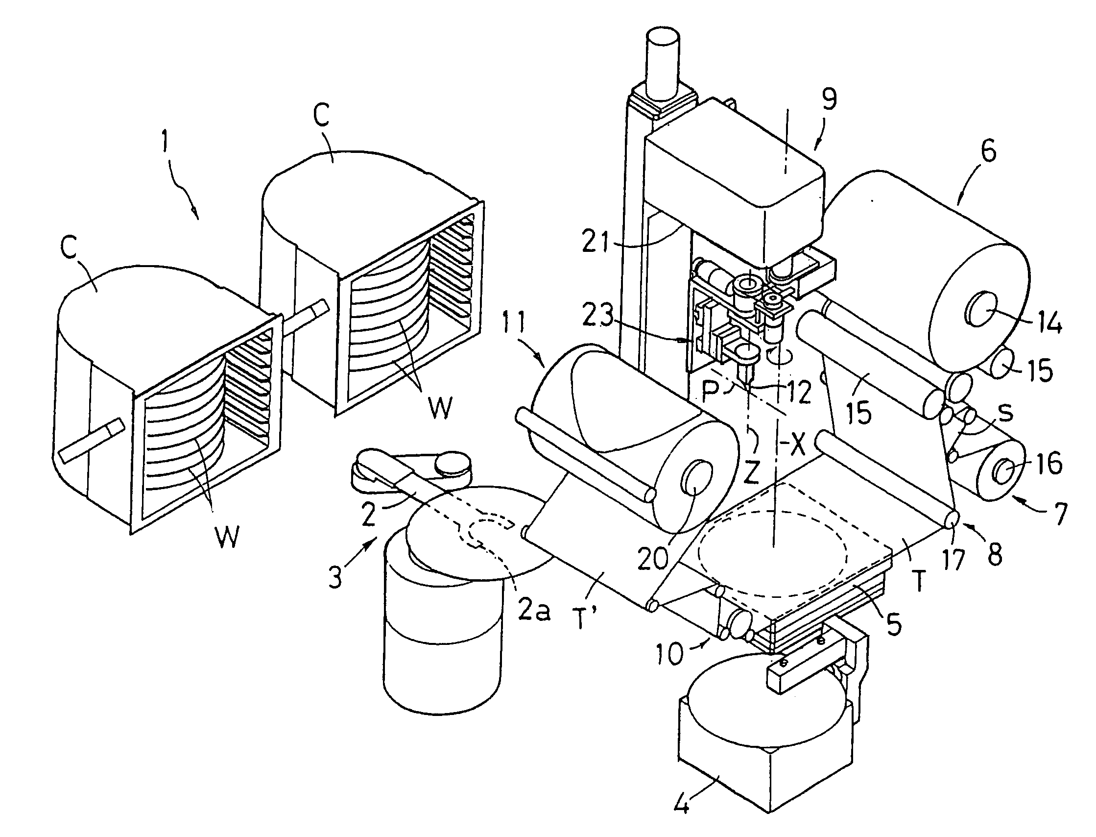
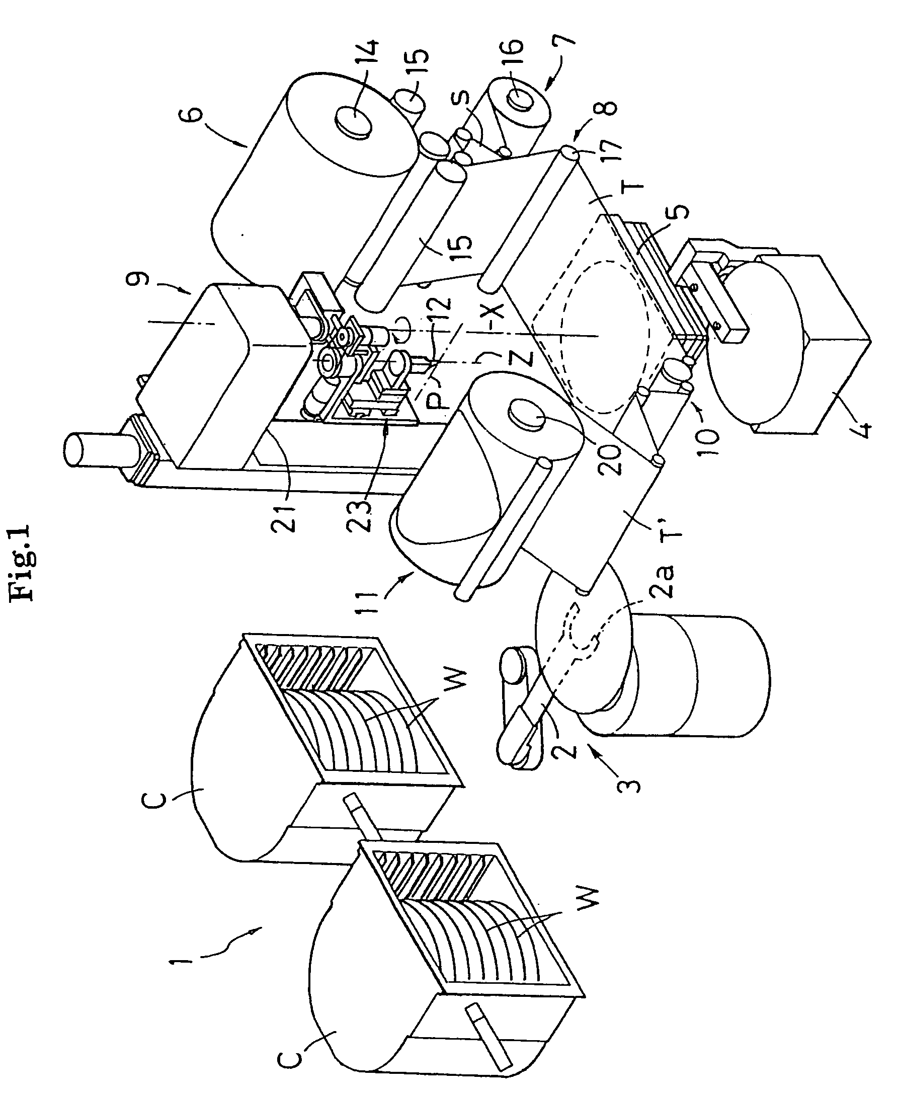
[0061]FIG. 1 is a perspective view showing the entire configuration of a protective tape joining apparatus. The protective tape joining apparatus comprises a wafer supplying / collecting unit 1, in which cassettes C containing semiconductor wafers (hereinafter, simply referred to as “wafers”) W therein are installed, a wafer transporting mechanism 3 provided with a robot arm 2, an alignment stage 4, a chuck table 5 for adsorbing and holding the wafer W mounted thereon, a tape supplying unit 6 for supplying a protective tape T with a separator s for protecting a surface of the wafer W onto the wafer W, a separator collecting unit 7 for separating the separator s from the protective tape T supplied from the tape supplying unit 6, and collecting the separator s, a joining unit 8 for joining the protective tape T onto the wafer W sucked and held by the chuck table 5, a tape c...


PUM

PropertyMeasurementUnit
angleaaaaaaaaaa
crossing angleaaaaaaaaaa
distancesaaaaaaaaaa

Abstract

In a method for allowing a cutter blade to relatively travel along an outer periphery of a semiconductor wafer to cut a protective tape joined to a surface of the semiconductor wafer in conformity with an outer shape of the semiconductor wafer, the cutter blade is allowed to relatively travel along the outer periphery of the semiconductor wafer with a positioning notch provided on the outer periphery thereof. The cutter blade is rotationally turned at the fore half of the notch recessed on the outer periphery of the semiconductor wafer during the relative travel of the cutter blade in such a manner that its blade tip is directed toward the center of the wafer. In contrast, the cutter blade is rotationally turned at the rear half of the notch in such a manner that its blade tip is directed toward the outer periphery of the semiconductor wafer.

Description

BACKGROUND OF THE INVENTION [0001] (1) Field of the Invention [0002] The invention relates to a method and apparatus for joining a protective tape. Herein, a protective tape is joined onto a semiconductor wafer mounted on and held by a chuck table. Thereafter, a cutter blade is allowed to travel along an outer periphery of the semiconductor wafer in a state where the cutter blade sticks out of the joined protective tape, so that the joined protective tape is cut in conformity with an outer shape of the semiconductor wafer. [0003] (2) Description of the Related Art [0004] A method for cutting a protective tape joined onto a surface of a semiconductor wafer is as follows. A protective tape is supplied onto a surface of a semiconductor wafer mounted on and held by a chuck table, and then, is joined onto the surface of the semiconductor wafer by rolling a joining roller on a non-adhesive face of the protective tape. Thereafter, a cutter blade is allowed to relatively travel along an out...

Claims


Application Information

Patent Timeline
Patent Type & Authority Applications(United States)
IPC IPC(8): B32B37/00B32B38/04B29C65/00
CPCB26D3/02B26D3/10B29C63/02B29C2793/00Y10T156/108H01L21/67132Y10T156/1052Y10T156/12H01L21/67092Y10T83/0259Y10T83/04Y10T83/05H01L21/50
Inventor YAMAMOTO, MASAYUKIMORI, NORIONISHINOHAMA, TAKASHIOGAWA, ATSUSHI
Owner NITTO DENKO CORP
Why Eureka
Try Eureka