Sorting device for coin tester

Inactive Publication Date: 2006-02-23
WALTER HANKE MECHANISCHE WERKSTATTEN
View PDF7 Cites 0 Cited by
  • Summary
  • Abstract
  • Description
  • Claims
  • Application Information

AI Technical Summary

Benefits of technology

[0003] It is therefore the object of the invention to provide a sorting device according to the preamble of the main claim which al

Problems solved by technology

Such a sorting device has the disadvantage that the thickness of the sorting device is quite noticeable due to the tension rod.
Furthermore, electromagnets with tension rods with regard to the cost of manufacture are very much more expensive fo

Method used


Image

  • Sorting device for coin tester
  • Sorting device for coin tester
  • Sorting device for coin tester

Examples


Example

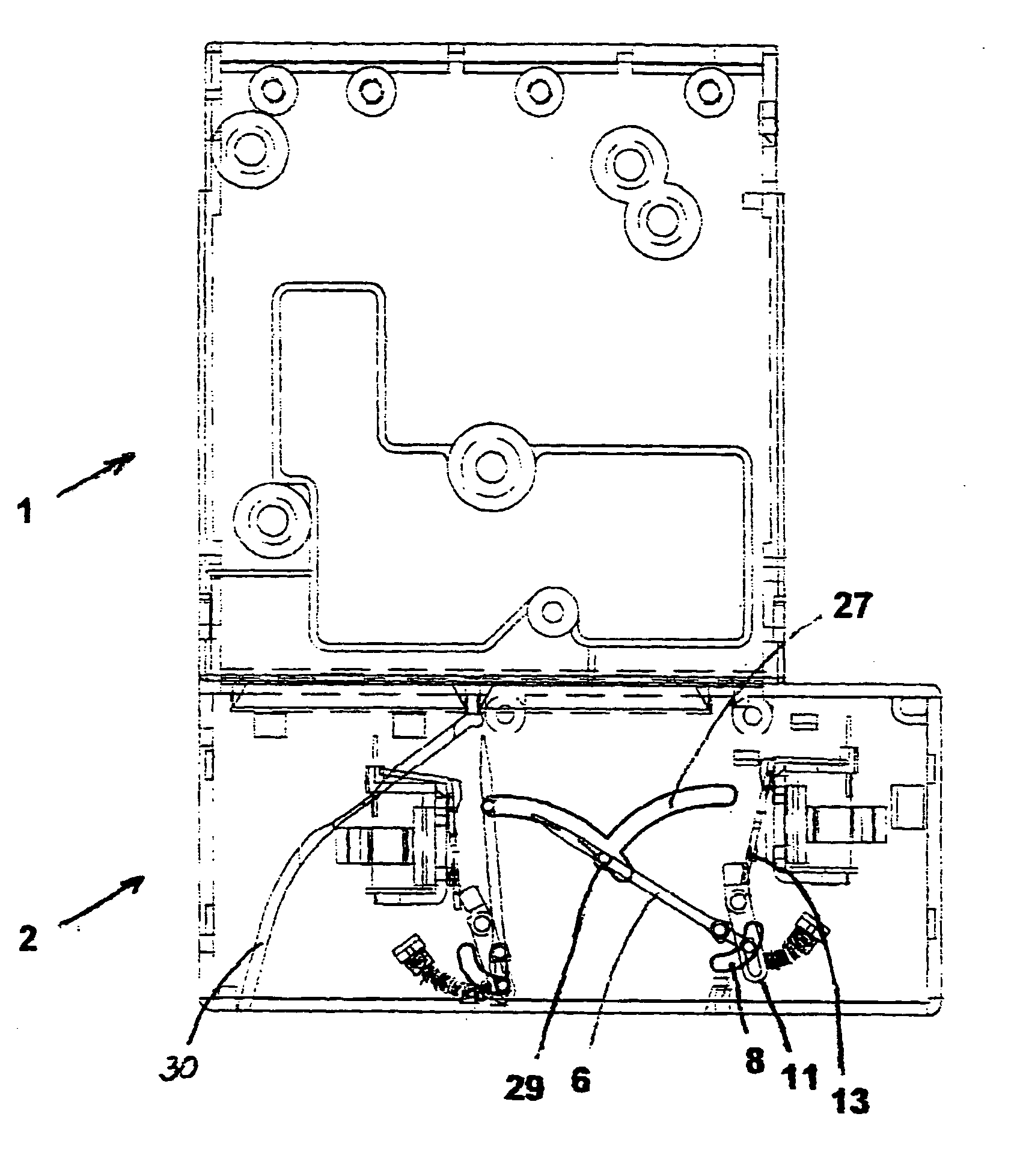
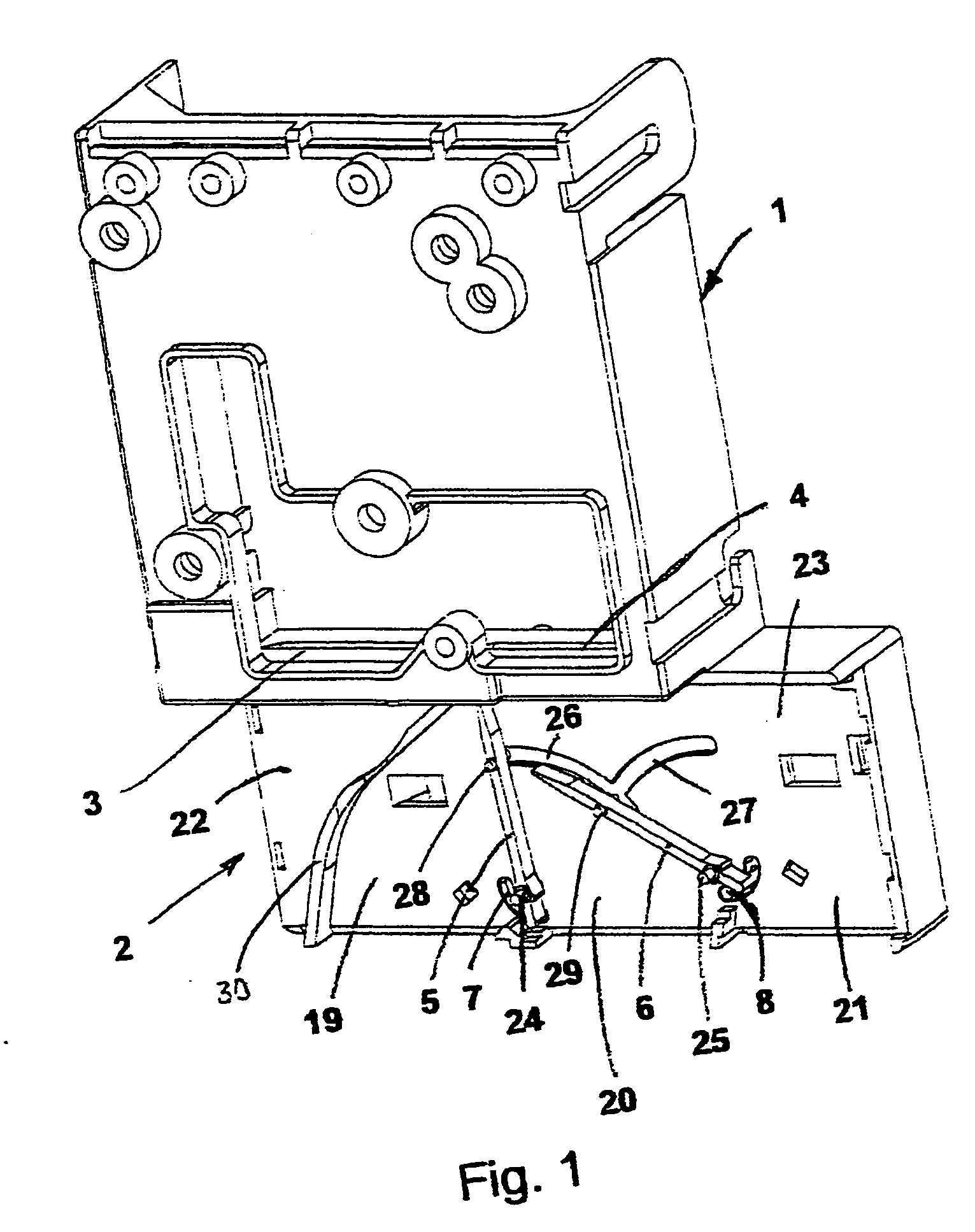
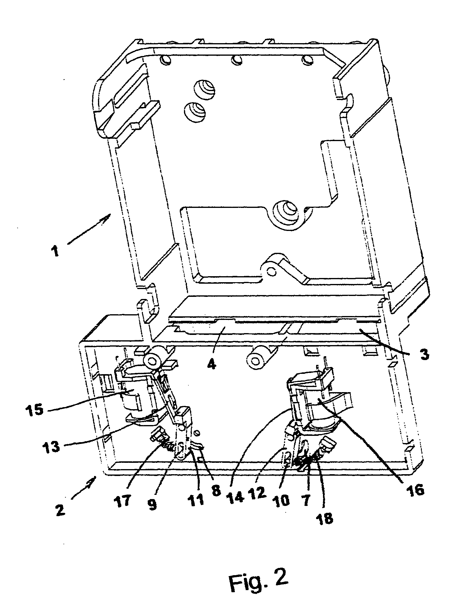
[0013] The arrangement of a sorting device represented in FIG. 1 to FIG. 4 comprises a frame 1 which serves for accommodating a coin tester, and a sorting unit 2 which is connected to the frame 1 as one piece.

[0014] Openings 3, 4 are provided between the frame 1 and the sorting unit 2 which serve for leading the coins which exit the coin tester further to the sorting unit. A curved, downwardly directed coin path 30 is located below the opening 3 and guides a coin which has not been accepted into the return provided on a narrow side of the sorting unit 2.

[0015] The view of the deflection levers 5, 6 is to be seen in FIG. 1, which where appropriate deflect the arriving coins in the respective direction. The deflection levers 5, 6 in each case with their lower end on which a projection is outwardly formed engage through an arch-like opening 7, 8, and as is to be seen in FIG. 2, engage in an elongate hole 9, 10 of a multiplication lever 11, 12. The multiplication levers 11, 12 in each...


PUM


Abstract

A sorting device for a coin tester, with a frame for fastening the coin tester and a sorting unit arranged on the frame which comprises at least one opening for the passage of a coin exiting from the coin tester is suggested. Elements which may be actuated by way of electromagnets are provided in the sorting unit and these elements release or block various coin paths depending on the activation of the electromagnets. The movable elements are designed as deflection levers which are pivotable in the plane of the running direction of the coins, are articulated to one another at a distance which is seen as transverse to the running direction, and are guided in arch-shaped guides.

Description

BACKGROUND OF THE INVENTION [0001] The invention relates to a sorting device according to the preamble of the main claim. [0002] Sorting devices are generally connected to coin testers and guide a coin exiting from the coin tester into a suitable channel or coin path. Deflection elements are provided for the guiding which may be actuated by a control via electromagnets. Such a sorting device for example is disclosed in EP 0 511 150 B1. With this, the deflection elements are moved linearly, i.e. perpendicular to the plane in which the running direction of the respective coin lies, by way of an electromagnet with a tension rod. Such a sorting device has the disadvantage that the thickness of the sorting device is quite noticeable due to the tension rod. Furthermore, electromagnets with tension rods with regard to the cost of manufacture are very much more expensive for example compared to flap armature (electro)magnets. Furthermore the movement of the tension rod must be effected in a...

Claims


Application Information

Patent Timeline
IPC IPC(8): G07D5/08G07F1/04
CPCG07D3/14
Inventor GRIESE, ROLAND
Owner WALTER HANKE MECHANISCHE WERKSTATTEN
Why Eureka
Try Eureka