Cable tray system

a cable tray and support plate technology, applied in the field of cable management systems, can solve the problems of inefficiency of the system, limited adaptability of junction plates, and plate not providing any way to maintain continuous

Inactive Publication Date: 2006-02-23
GS METALS
View PDF31 Cites 48 Cited by
  • Summary
  • Abstract
  • Description
  • Claims
  • Application Information

AI Technical Summary

Benefits of technology

[0008] In the present invention, brackets are provided that both hold wire mesh support trays and provide th...

Problems solved by technology

This system is inefficient, however, since it requires two separate connections to the trays (one to the bracket for supporting the tray and the other with separate clips attaching the trays to each other).
The known junction plates have limited adaptability because they do not provide a way for consecutive wire mesh trays to be placed directly next to each other in all possible directions (fo...

Method used


Image

  • Cable tray system
  • Cable tray system
  • Cable tray system

Examples


Embodiment Construction

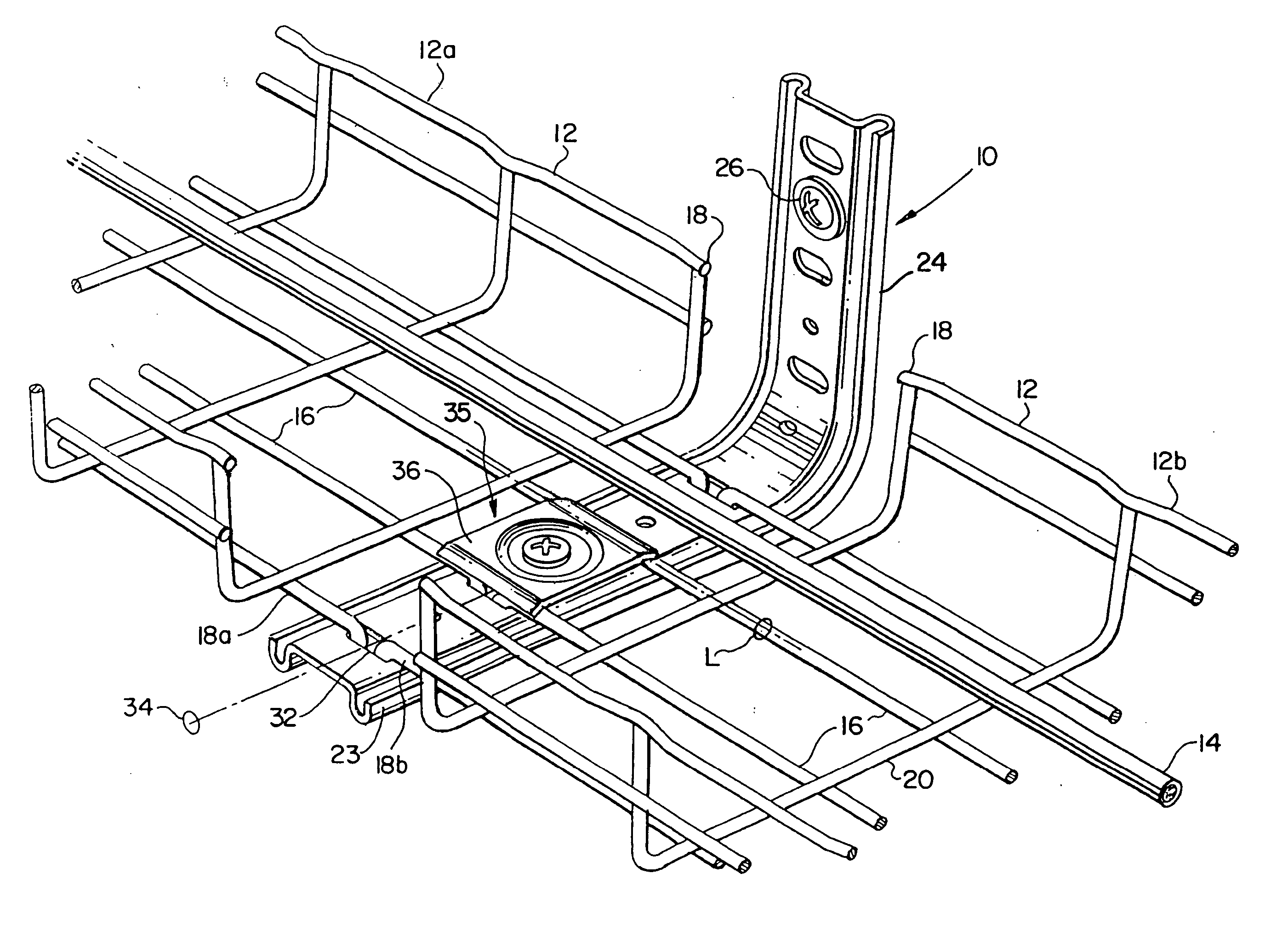
[0030] A cable support system, indicated in general at 10 in FIGS. 2 and 3A, is typically used for sub-floor or above-ceiling support of cable networks. The system, however, is not limited to one particular use or position. The cable support system 10 includes a number of support trays 12 placed end-to-end along the paths of a cable or cables 14 that they are to support. As shown in FIG. 3A, in a chain of support trays 12 along the path for a cable 14, a single bracket 24 will support the trays 12 at each joint between adjacent trays. The bracket 24 can also be used at the end of a chain of trays to support a single support tray.

[0031] As shown in FIGS. 1-4, the support trays 12 preferably are wire mesh and have longitudinal or main wires 16 that extend from at least one end 18 of each support tray 12. Here, the wire mesh trays also have a number of transverse wires 20 forming the wire mesh.

[0032] The main wires 16 have bent hook ends 22 (shown in FIGS. 4B and 8-10) for connecting...


PUM


Abstract

A cable support system has a support bracket with an elongated member defining a longitudinal central axis. The member also defines at least one slot with its longest dimension transverse to the central axis. At least two adjacent support trays are provided and each have an end secured to the bracket. Each tray end has a wire with a bent hook end where the two hook ends oppose each other at the bracket. The slot engages both hook ends. A fastening mechanism is provided for securing both tray ends to the elongated member.

Description

TECHNICAL FIELD OF THE INVENTION [0001] The invention relates generally to cable management systems, and more particularly to wire mesh cable support trays that are interconnected at improved support brackets. BACKGROUND OF THE INVENTION [0002] Cable tray systems are known for supporting a network of cables below raised floors or above hung ceilings and other areas where cable networks are located. The conventional cable tray system is made of a large number of trays or modules positioned end to end along the desired route where cables are to placed and supported. The cable trays, in turn, are supported by a number of brackets or hangers mounted on posts (sub-floor posts holding up a raised floor or any other columns), walls, ceilings, floors or other building structures. The trays are connected to each other by separate clips or clamps. [0003] As shown in FIG. 1, one conventional design has a support bracket 200 that holds a wire mesh tray 202. A clamp plate 204 with a slot in its ...

Claims


Application Information

Patent Timeline
IPC IPC(8): F16L3/00
CPCH02G3/0443H02G3/263H02G3/0608
Inventor WINN, GREGGMCCRARY, TERRYOHMS, DONALD
Owner GS METALS
Why Eureka
Try Eureka