Monitoring apparatus with connector

a technology of monitoring apparatus and connector, which is applied in the direction of lighting apparatus, electrical apparatus, light sources, etc., can solve the problems of inconvenient maintenance, inability to climb on a high or low place, and inability to avoid later maintenance, etc., and achieve the effect of convenient maintenan

Inactive Publication Date: 2006-02-23
YEH MING HSIANG
View PDF5 Cites 23 Cited by
  • Summary
  • Abstract
  • Description
  • Claims
  • Application Information

AI Technical Summary

Benefits of technology

[0004] The main purpose of the present invention is to provide a monitoring apparatus with a connector in which a lamp head type connector is utilized to mount the present invention directly on the lamp socket. The present invention can be operated to perform the monitoring step through electric power supplied by the lamp socket, and can be coupled to a lamp to provide with an illumination function, thus dual purposes including illumination and monitoring purposes can be achieved. Accordingly, the assembling step can be accomplished readily due to no wiring. The present invention with easy maintenance is suitable to be mounted on a high and faraway place.
[0005] Another purpose of the present invention is to provide a monitoring apparatus with a connector; the present invention can be mounted directly on the lamp socket through a power plug type connector without additional electric cord. Thus, it is convenient to assemble and maintain the present invention.
[0013] Thus, the present invention can be mounted directly on several indoor lamp sockets through lamp head type connectors, or inserted into sockets through power plug type connectors. Once electric power is supplied, the present invention can be operated as a lamp to illuminate and to achieve the monitoring purpose. Thus, the monitoring apparatus with simple assemblage and maintenance is provided.

Problems solved by technology

Since wiring of power distribution is needed for these monitors, climbing on a high or low place cannot avoid.
It is very inconvenient.
After the monitors are mounted, the later maintenance, which is concerned with wiring, is inconvenient.

Method used


Image

  • Monitoring apparatus with connector
  • Monitoring apparatus with connector
  • Monitoring apparatus with connector

Examples


Embodiment Construction

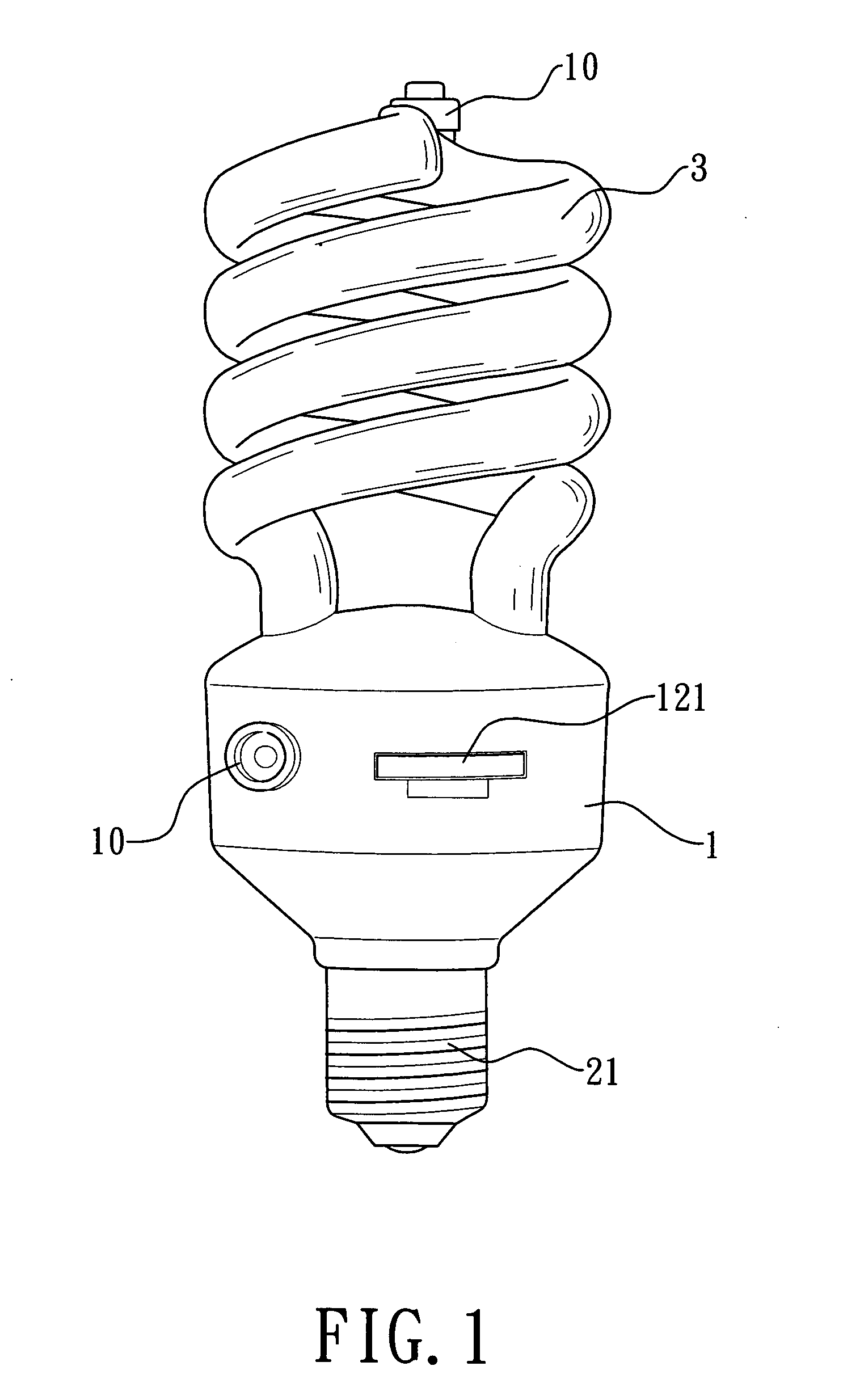
[0025]FIG. 1 is a schematic diagram showing an outward-appearance of the present invention. As shown in FIG. 1, the present invention comprises a main body 1 as a monitoring apparatus. A connector, which is a lamp head 21 to be mounted on the lamp socket, is mounted on one end of the main body 1. A lamp 3, which is a bulb or a tube, is mounted on the other end of the main body 1. The lamp 3 is electrically connected to the lamp head 21 to provide with the function of illumination.

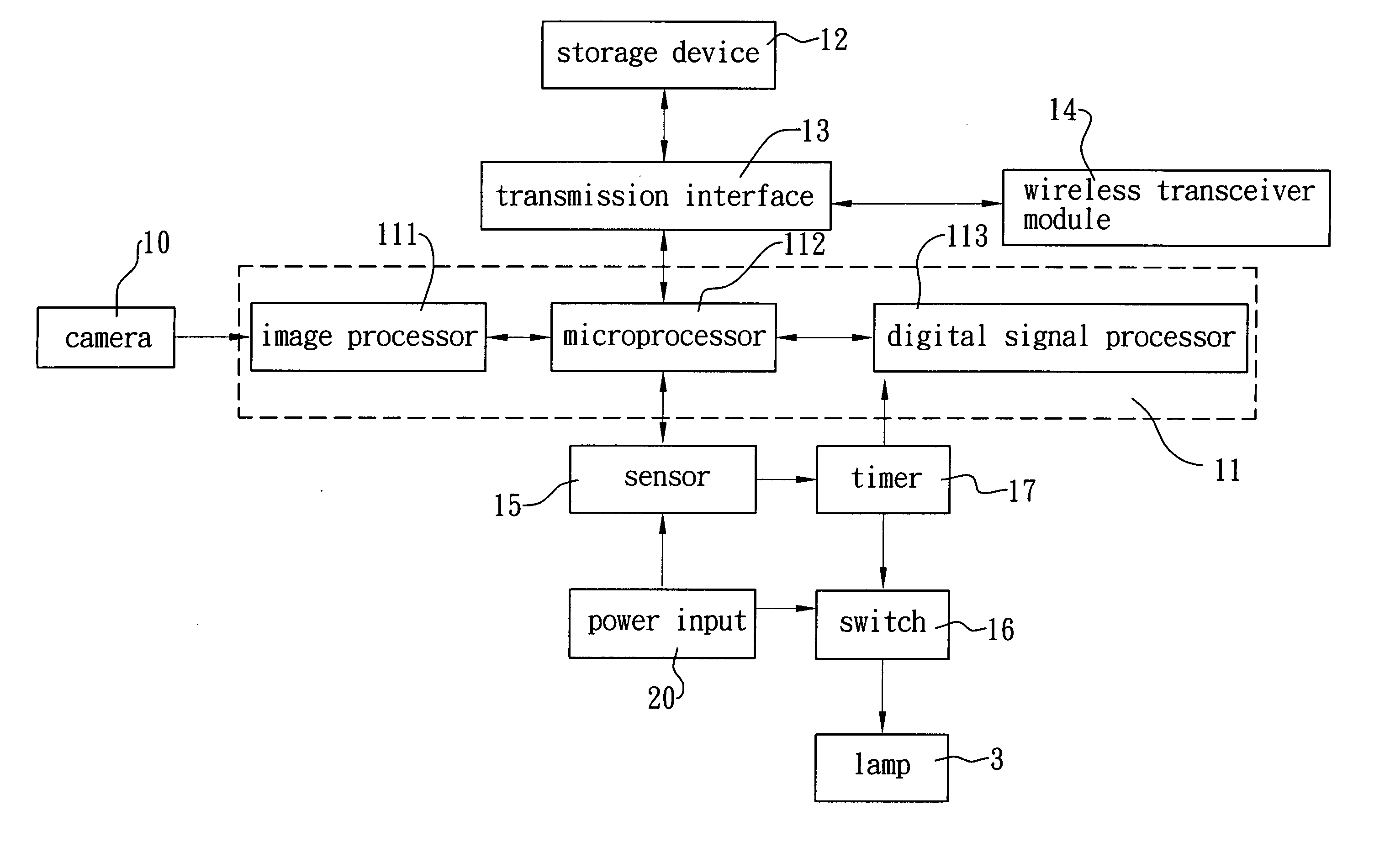
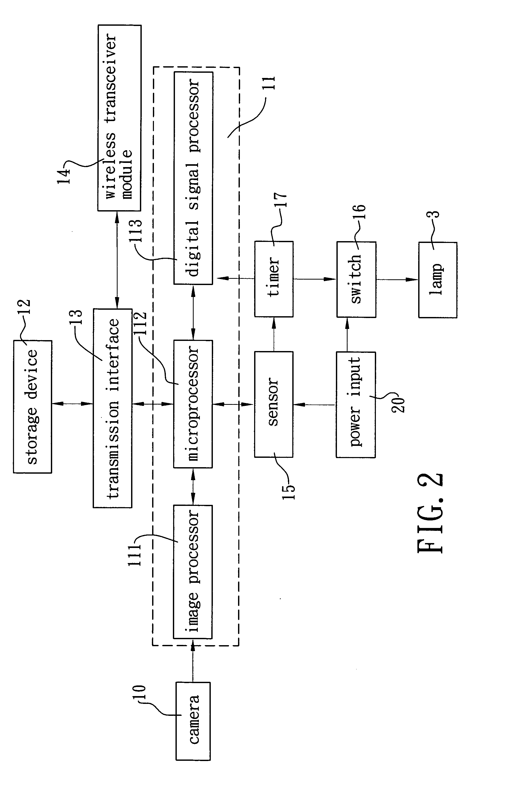
[0026]FIG. 2 is a block diagram showing a composition of the present invention. As shown in FIG. 2, the main body 1 is a monitoring apparatus. A camera 10 for capturing image is mounted on the main body 1. The camera 10 can be also mounted on the lamp 3 to capture images from different locations and angles.

[0027] A processing control unit 11, which is used for processing and controlling signal data, comprises an image processor 111 connected to the camera 10 for processing and compressing the captured ima...


PUM


Abstract

A monitoring apparatus with a connector is disclosed. The monitoring apparatus is inserted directly into a device, such as bulb socket or power socket, to which electric power has been supplied thereby the monitoring apparatus can be operated automatically through the supplied electric power. The present invention comprises a main body used as a monitoring apparatus. A camera is mounted on the main body 1 to capture an image transmitted to a processing control unit for processing and transmitted outwardly through a wireless transceiver module to achieve the monitoring purpose. Thereafter, the captured image can be stored into a storage device. A connector is mounted on one end of the main body 1, the connector can be a lamp head to be mounted directly on a lamp socket, and the connector can be a power plug to be inserted into a power socket for obtaining electric power. The main body can be connected to a lamp to provide with the illumination purpose at the same time. The present invention can be directly mounted without wiring. Thus, the present invention can be assembled easily, and is suitable to be mounted at a high and faraway place. Moreover, it is convenient to maintain the present invention.

Description

BACKGROUND OF THE INVENTION [0001] The present invention relates to a monitoring apparatus with connector, and more particularly to a connector that is mounted directly on a device, for example, a bulb socket or a power socket, to which electric power has been supplied, and no wiring is required for operation by using the device to which electric power is supplied. [0002] Monitors are always mounted on public places, buildings, stores, or residence houses. In order to monitor various locations, monitors are usually mounted on every indoor and outdoor nook, and mostly on the high places. Since wiring of power distribution is needed for these monitors, climbing on a high or low place cannot avoid. It is very inconvenient. After the monitors are mounted, the later maintenance, which is concerned with wiring, is inconvenient. [0003] Further, bulb sockets, which are used to provide with illumination, are generally mounted on every location of the stores, display place, or inside of build...

Claims


Application Information

Patent Timeline
Patent Type & Authority Applications(United States)
IPC IPC(8): H05B37/02
CPCH05B37/0272H05B47/195
Inventor YEH, MING-HSIANG
Owner YEH MING HSIANG
Why Eureka
Try Eureka