
Method and apparatus for bandwidth management of aggregate data flows

a technology of aggregate data flow and bandwidth management, applied in the field of digital data transmission, can solve the problems of inefficient bandwidth use of data packets, small headers envisaged for mpls, and control of tcp/ip flow connection

Inactive Publication Date: 2006-02-23
CIENA
View PDF3 Cites 88 Cited by
  • Summary
  • Abstract
  • Description
  • Claims
  • Application Information

AI Technical Summary

Benefits of technology

[0008] The transmission device can detect and react to congestion within the network and allows for rate regulation of the aggregate flow without adding marking data to every existing packet.

Problems solved by technology

Unfortunately, adding more headers to data packets is inefficient in bandwidth use and may be problematical if the longer packets violate Maximum Transport Unit (MTU) limits.
Unfortunately, the small header envisaged for MPLS does not provide room for the information usually carried in a TCP / IP flow controlled connection.

Method used


Image

  • Method and apparatus for bandwidth management of aggregate data flows
  • Method and apparatus for bandwidth management of aggregate data flows
  • Method and apparatus for bandwidth management of aggregate data flows

Examples


Embodiment Construction

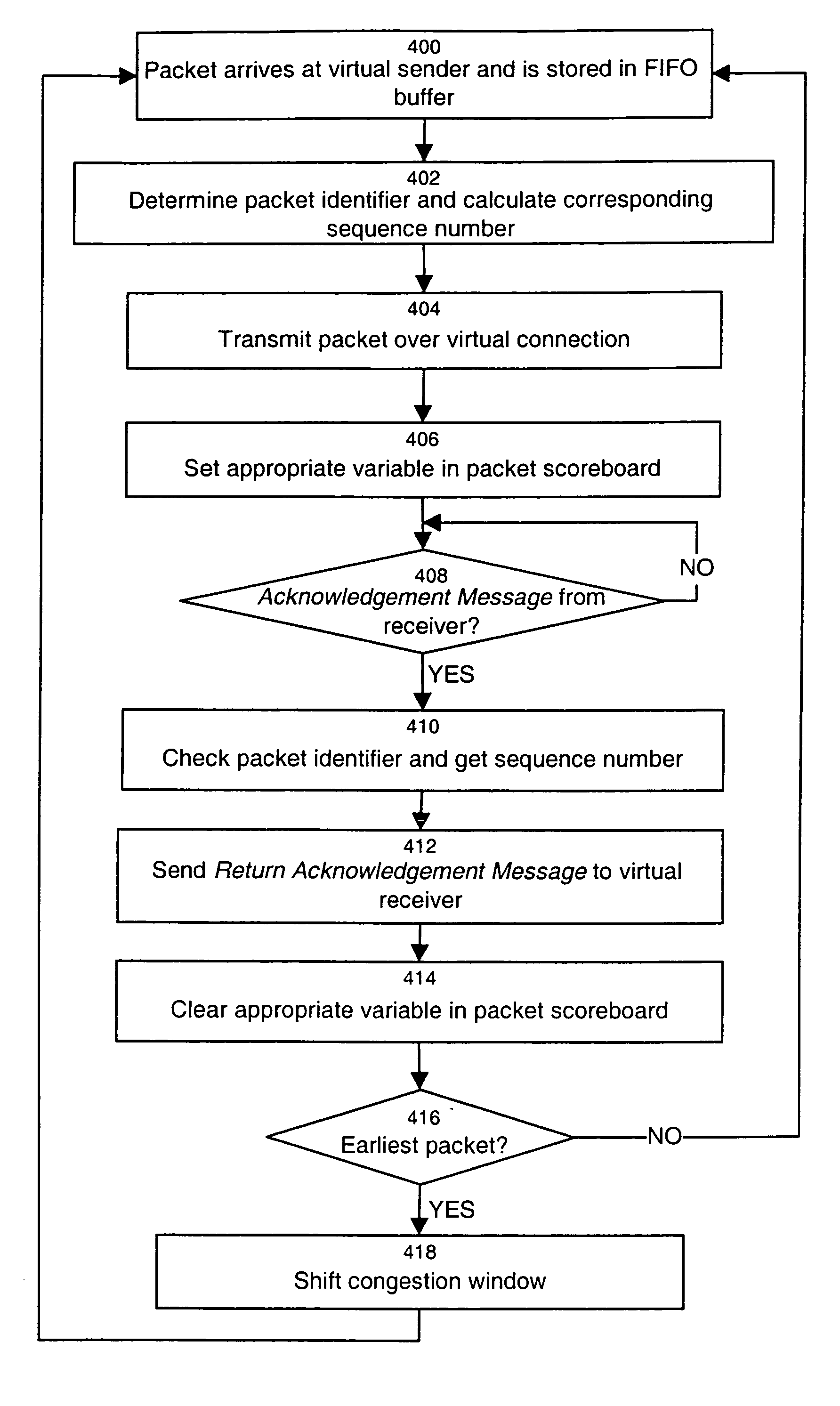
[0018] A conventional IP network implements bandwidth sharing among host machines using the Transport Control Protocol (TCP). Although data flow in the network can be bi-directional, it is usual to refer to the originator of a particular piece of data as the sender and the other end as the receiver. In TCP, the sender (sender host machine) constantly tests the network to see if more bandwidth is available and uses the loss of a packet determined by sequence numbers of TCP packets as an indication to decrease its rate. Any lost packets are sent again so that there is a reliable flow of traffic. The loss of too many packets can cause the TCP connection to enter the timed out state.

[0019] Each packet contains a sequence number, which increases according to the number of bytes transmitted. The receiver acknowledges packets using this numbering scheme and always acknowledges the latest packet received in correct sequence. It may acknowledge each packet individually or wait in order to r...


PUM


Abstract

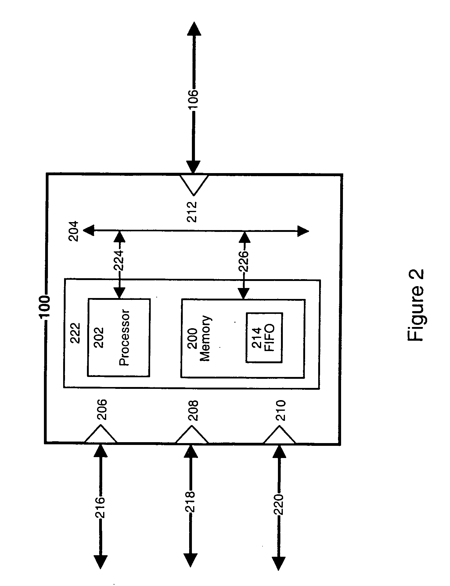
The present invention relates to a transmission device implementing a flow control mechanism for aggregate trunks. The transmission device can be implemented as a router that includes an input for receiving aggregate traffic streams, an output for releasing the aggregate traffic streams to a destination point and a control unit capable to regulate the rate of release of packets from the output. Specifically, the flow control operation effected by the control unit is dependent on receipt of acknowledgement messages issued at the destination point, each acknowledgement message confirming the receipt of one or more particular packets at the destination point. The control unit will continuously increase the packet sending rate until a packet is lost in the network between the transmission device and the destination point. On detection of packet loss, based on the lack of one or more corresponding acknowledgement messages from the destination point, the control unit will reduce the packet sending rate.

Description

FIELD OF THE INVENTION [0001] The present invention relates to the field of digital data transmission. More specifically, it pertains to a method and apparatus for performing traffic management functions, such as bandwidth management of aggregate traffic streams between two points of a data transport network. BACKGROUND OF THE INVENTION [0002] A typical data transport network operates in a connectionless mode whereby there is no negotiation between the transmitter / receiver and the network with regard to the type or quantity of traffic that is to be sent. The transmitter simply sends the traffic on the network, and relies on the network components to deliver that traffic to the receiver accurately. These network components consist typically of routing nodes (also known as routers or switches) joined by physical links. The main function of the routing nodes is to direct incoming packets to the appropriate outgoing links. [0003] Many communication network applications have adopted the ...

Claims


Application Information

Patent Timeline
IPC IPC(8): H04J1/16H04L1/18H04L29/08H04L1/16H04L12/56H04L29/06
CPCH04L1/16H04L47/10H04L47/263H04L69/162Y02B60/31H04L69/16H04L69/163H04L47/27Y02D30/50
Inventor CHAPMAN, ALAN STANLEY JOHNKUNG, HSIANG-TSUNG
Owner CIENA
Learn More