
Fluid dynamic bearing motor attached at both shaft ends

a technology of fluid dynamic bearings and motors, applied in the direction of bearings, shafts and bearings, rotary bearings, etc., can solve the problems of increasing the risk of lubricant leakage out of the fluid dynamic bearing, the design of all known fluid dynamic bearing designs for the motor attached at both ends is not easy to realize, and the effect of high precision

Inactive Publication Date: 2006-02-23
KURA LAB
View PDF9 Cites 51 Cited by
  • Summary
  • Abstract
  • Description
  • Claims
  • Application Information

AI Technical Summary

Benefits of technology

The present invention provides a fixed shaft type fluid dynamic bearing structure that is suitable for use in low profile motors. This structure can achieve high precision driving of magnetic disks or similar devices.

Problems solved by technology

The technical problem addressed in this patent text is to create a fluid dynamic bearing motor for low-profile hard disk drives that is attached at both ends of the housing, and can achieve a low non-repetitive runout during rotation while also preventing lubricant leakage and addressing the various challenges that arise when trying to seal the lubricant. Existing solutions have not been easy to achieve and have resulted in high costs and manufacturing imperfections.

Method used


Image

  • Fluid dynamic bearing motor attached at both shaft ends
  • Fluid dynamic bearing motor attached at both shaft ends
  • Fluid dynamic bearing motor attached at both shaft ends

Examples


first embodiment

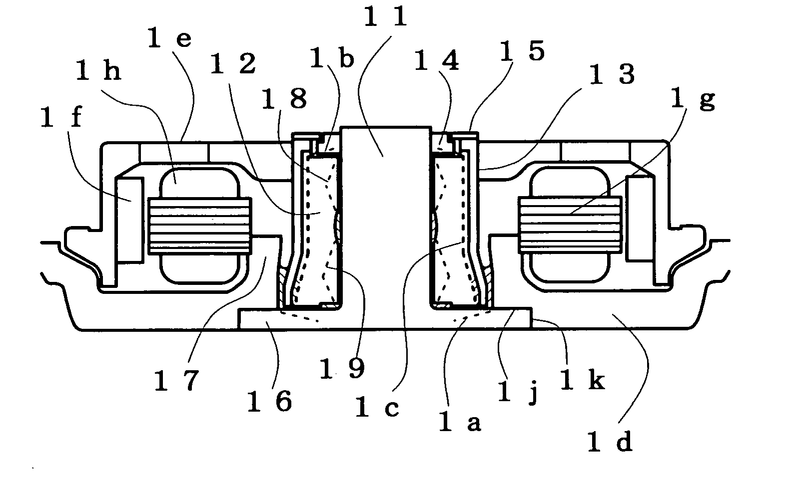
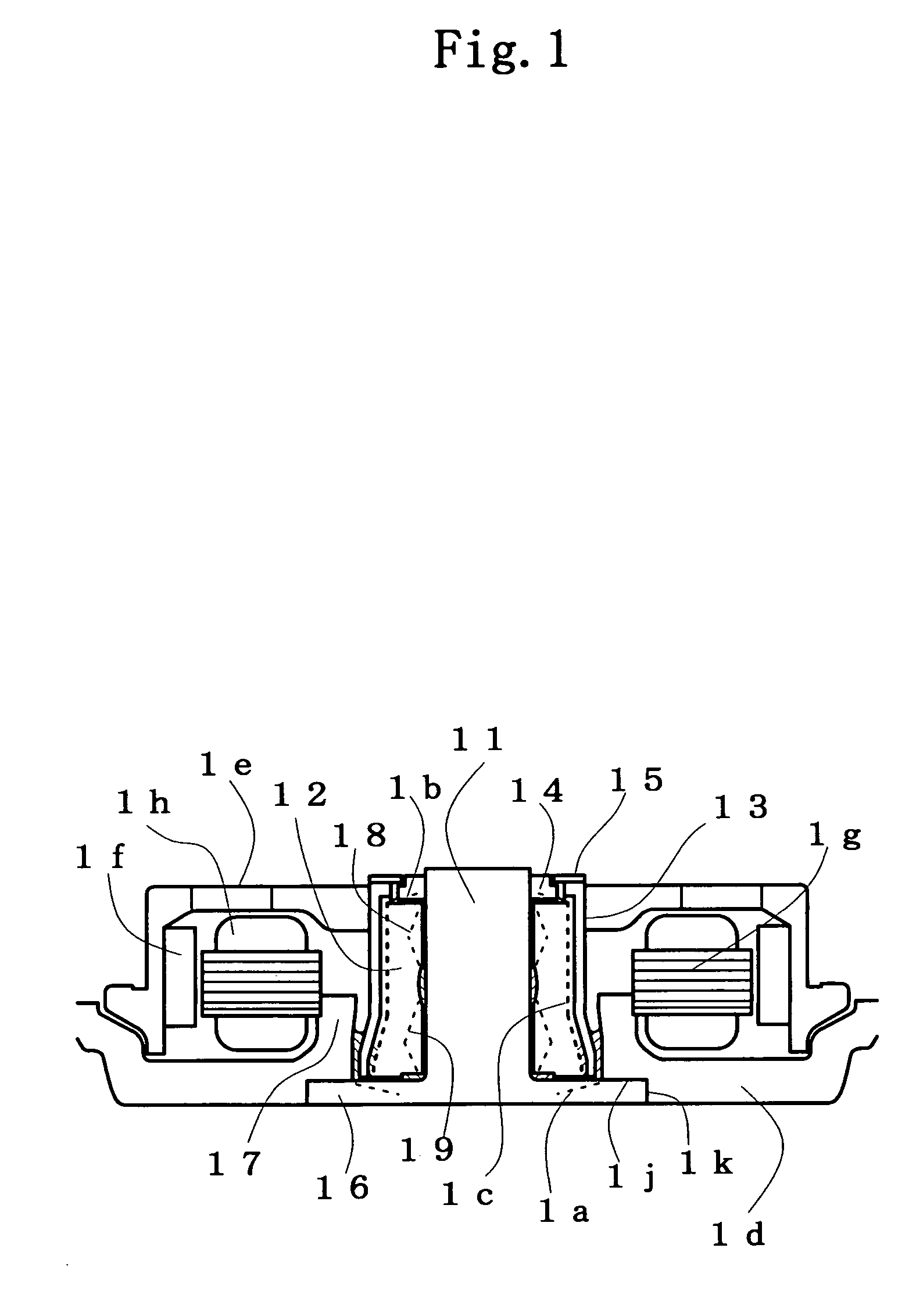
[0057]FIG. 1 is a vertical sectional view of a fixed shaft type fluid dynamic bearing motor which is the present invention.

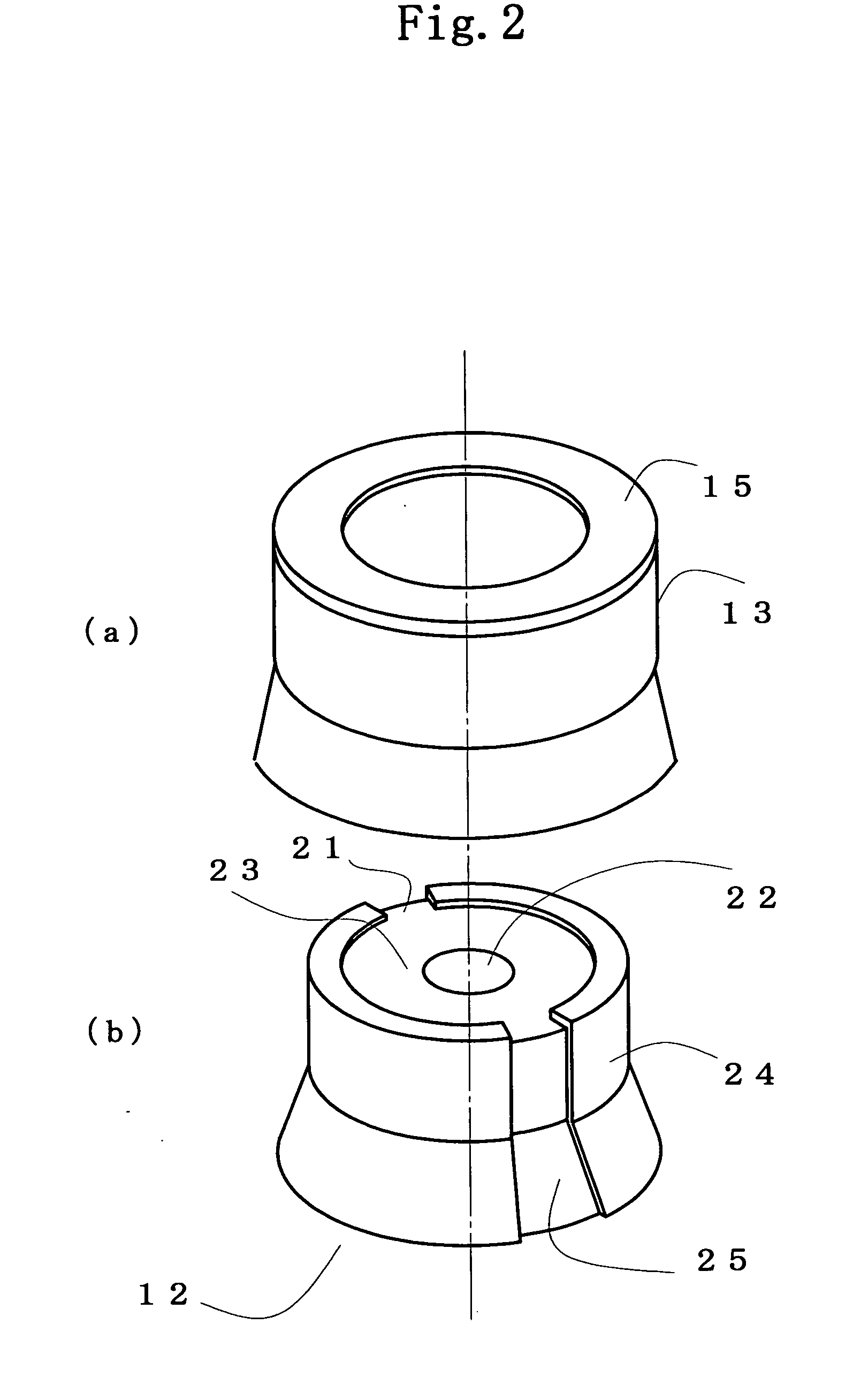
[0058] A fixed shaft 11 is a T-shaped cylindrical shaft which is composed of a cylindrical shaft and a flange 16. The sleeve, which rotatably fits to a T-shaped cylindrical shaft 11, is composed of an inner cylinder 12 and an outer cylinder 13. The upper and lower end surfaces of the inner cylinder 12 are opposing the first annular member 14 which is fixed to the shaft 11 and the flange 16 with small gap respectively.

[0059] The second annular member specified in claim 1 corresponds to the flange 16 and the part 17 of the base plate 1d (hereinafter, referred to as an annular member 17). The numeral 1c represents channels formed in the sleeve and having an intake portion near the outer region of the first annular member 14 and an outlet portion near the periphery of the bottom end of the sleeve. A lubricant is continuously filled into the gap between the shaft 11...


PUM


Abstract

A fixed shaft type fluid dynamic bearing motor having two interfaces of a lubricant at least, in which a channel leading from near the outer region of a rotating sleeve top end to near the periphery of the bottom of the sleeve is formed in the sleeve. The lubricant near the outer region of a rotating sleeve top end is thrown out into the channel by centrifugal force, and further conveyed to near the periphery of the bottom of the sleeve by centrifugal force and/or by slanted channel in circumferential direction. A dynamic-pressure generating groove for pumping the lubricant toward the top end of the sleeve is formed between the fixed shaft and the sleeve. The dynamic-pressure generating groove and the centrifugal force cause the circulation of the lubricant, thereby sealing the lubricant. According to the invention, axial space smaller than that of tapered seals can be utilized to achieve a low-profile recording disk drive.

Description


Claims


Application Information

Patent Timeline
Owner KURA LAB
Learn More