Image forming system and image forming apparatus

a technology of image forming system and image forming apparatus, which is applied in the direction of electrographic process apparatus, instruments, printing, etc., can solve the problems of large amount of consumables and time loss, and achieve the effect of reliable reporting information

Inactive Publication Date: 2006-02-23
CANON KK
View PDF4 Cites 81 Cited by
  • Summary
  • Abstract
  • Description
  • Claims
  • Application Information

AI Technical Summary

Benefits of technology

[0010] Another object of the present invention is to provide an image forming system and an image forming apparatus that are capable of reliably reporting inf

Problems solved by technology

However, in a market of print on demand (POD) where a large amount of printing jobs are simultaneously handled, there is a case where during execution of one printing job, another printing job is inputted to occupy the image forming apparatus for a long time and consume a large a

Method used


Image

  • Image forming system and image forming apparatus
  • Image forming system and image forming apparatus
  • Image forming system and image forming apparatus

Examples


first embodiment

[0093]

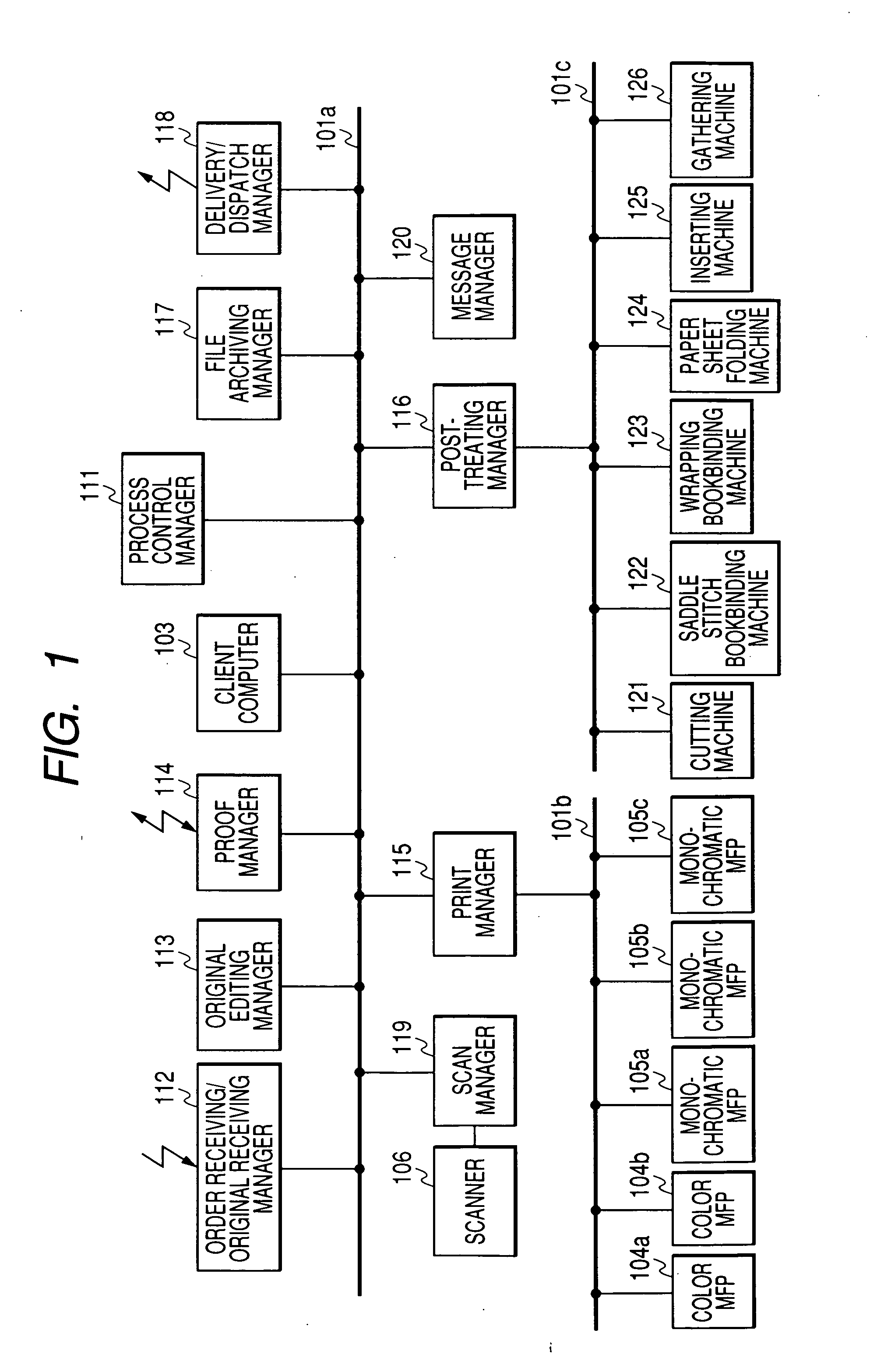
[0094]FIG. 1 is a block diagram showing an example of a configuration of an image forming system according to this embodiment.

[0095] In FIG. 1, the image forming system is provided with a process control manager 111; an order receiving and original receiving manager 112; an original editing manager 113; a proof manager 114; a client computer 103; a file archiving manager 117; a delivery and dispatch manager 118; a scanner 106; a scan manager 119; a print manager 115; a post-treating manager 116; and a message manager 120. In addition, the image forming system is provided with Multi Function Peripherals (MFPs) 104 and 105; a cutting machine 121; a saddle stitch bookbinding machine 122; a wrapping bookbinding machine 123; a paper sheet folding machine 124; an inserting machine 125; and a gathering machine 126.

[0096] Respective portions which configure the image forming system is connected to each other via a network 101. The network 101 may be configured either by a plurality ...

second embodiment

[0449] The second embodiment of the present invention is different from the first embodiment as described above in the points mentioned below. The other elements of the second embodiment are the same as the corresponding elements of the first embodiment described above; and accordingly, the explanation thereof is omitted.

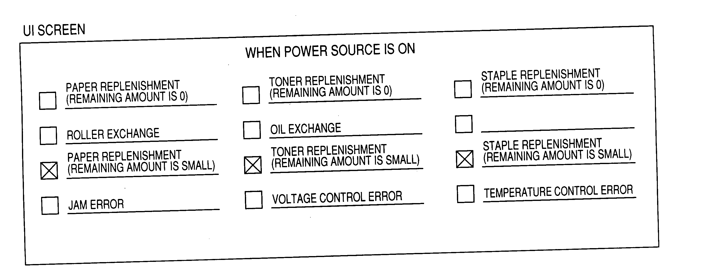
[0450] In the first embodiment as described above, the explanation is made as to a case where the determination of whether or not the message manager 120 displays the warning message is made based only on the maintenance information, the error information, potential value information, the exhaustion degree information of each of the parts, which require maintenance, of the printer device (the color MFP 104a, the color MFP 104b, the monochrome MFP 105a, the monochrome MFP 105b, and the monochrome MFP 105c) connected to the network 101.

[0451] In this embodiment, an explanation is made on a configuration in which the message manager 120 is also connected via the netw...

third embodiment

[0467] A third embodiment of the present invention is different from the first embodiment described above in the points as described below. Because the other elements of the third embodiment are the same as the corresponding elements of the first embodiment (FIG. 1) described above; therefore, the explanation thereof is omitted.

[0468] In the third embodiment of the present invention, considering that the state of the print job to be inputted to the image forming system varies from time to time, the timing at which the maintenance becomes necessary varies in real time depending on the state of a reception of a print job and the state of a reception of an order. In this regard, in this embodiment, a configuration is explained in which the timing at which the maintenance becomes necessary is predicted in accordance with the state of a reception of a print job and the state of a reception of an order, to thereby dynamically scheduling timings for displaying the warning message.

[0469]

[...


PUM


Abstract

Provided is an image forming system and an image forming apparatus capable of reliably reporting information relating to a remaining amount of consumables to an operator without increasing the number of operations of the operator of the image forming system. The image forming system connects a variety of kinds of managers such as a process control manager, an order receiving/original receiving manager, and a message manager, and post-treatment devices such as MFPs, a cutting machine, and a saddle stitch bookbinding device, via a network. The message manager reads the remaining amount of paper sheets of an applicable printer device from a consumption degree table which is stored in an HDD; computes an expected amount of consumption of the paper sheet of the applicable printer device to be consumed due to execution of a job; and when the remaining amount of the paper sheet is below 0 as a result of subtraction of the expected consumption amount of the paper sheet from the remaining amount of the paper sheet, displays on a UI a warning message indicating that an operator maintenance is necessary.

Description

BACKGROUND OF THE INVENTION [0001] 1. Field of the Invention [0002] The present invention relates to an image forming system and an image forming apparatus. [0003] 2. Related Background Art [0004] In a conventional image forming apparatus, printing performed by developing a latent image formed on a photosensitive member with a developer and by transferring and fixing the developed image to and on a paper sheet. Some image forming apparatuses of this kind display a warning message via a display device (UI: user interface) when time to replace a consumable such as the paper sheet and toner is near. Some are capable of notifying an operator of a timing of replacement of the consumable (for example, Japanese Patent Application Laid-Open No. H10-315590). [0005] However, in a market of print on demand (POD) where a large amount of printing jobs are simultaneously handled, there is a case where during execution of one printing job, another printing job is inputted to occupy the image formi...

Claims


Application Information

Patent Timeline
IPC IPC(8): G03G15/00G03G15/08
CPCB41J2/17546B41J11/0075G03G15/553G03G15/5083G03G15/55G03G15/5079G03G2215/00109G06F3/1203G06F3/121G06F3/1235G06F3/126G06F3/1275G06F3/1282G06F3/1285
Inventor MIMA, TSUYOSHI
Owner CANON KK
Why Eureka
Try Eureka