Coordinate input apparatus, coordinate input method, coordinate input-output apparatus, coordinate input-output unit, and coordinate plate

a technology of input apparatus and output screen, which is applied in the direction of mechanical pattern conversion, instruments, cathode-ray tube indicators, etc., can solve the problems of unstable detection, reduced brightness and clearness of display images, and increased area of input screen, etc., to achieve excellent reliability and operability, low cost, and high reliability of recorded coordinate information

Inactive Publication Date: 2005-11-15
CANON KK
View PDF40 Cites 54 Cited by
  • Summary
  • Abstract
  • Description
  • Claims
  • Application Information

AI Technical Summary

Benefits of technology

[0023]The present invention has been made in view of these situations, so that it is an object of the present invention to provide a coordinate input apparatus and a coordinate input-output apparatus with excellent reliability and operability and low cost. That is, the reliability of the recorded coordinate information is high, while eliminating reduction in the brightness (luminance) of display images, reduction in the clearness (resolution) of display images, increasing in the reflection of extraneous light, and reduction in the operability of input indication by being disturbed by the coordinate information when an operator can recognize it.

Problems solved by technology

Due to the means for generating each kind of physical phenomenon arranged in the input screen itself or between the input indicator and a part of the input screen, as described above, there has been a problem that the conventional coordinate input apparatus described above becomes extremely expensive when increasing the area (i.e., size) of the input screen.
That is, in the resistance tablet, the brightness and clearness of display images are reduced because of the insufficient light-transmission rate of the resistor such as an ITO forming the transparent resistor; in the magnetic coupling tablet and the capacitive coupling tablet, the loop-coil-shaped or line-shaped transparent electrode patterns arranged in the X and Y directions are liable to be electrically and magnetically affected by noises from a panel, a driving circuit, or a power supply circuit of the display apparatus, resulting in unstable detection or further increased cost due to the unstableness prevention.
Also, in the optical coupling tablet and the acoustic vibration tablet, there is an operational problem that when a hand of an operator or another article is placed into the transmission path of light, an acoustic wave, or an elastic wave, the detection performance is deteriorated or the detection cannot be established due to this effect.
However, in the conventional coordinate input apparatus described above and comprising the coordinate plate having coded coordinate information stored therein and the input indicator having means for detecting the coordinate information built therein, two problems arise as follows.
The first problem is about the reliability of the recorded coordinate information concerning the basic function of the coordinate input apparatus.
When the recorded coordinate information is damaged, deformed, worn out, paled, discolored, and dropped off, it is extremely difficult to maintain the precise detection.
Furthermore, the basic function of the coordinate input apparatus is damaged causing miss-detection or non-detectability.
For example, it is obvious that the input indicating means be abutted, pressed, or rubbed against the surface of the coordinate plate or the tablet by an operator during the operation, so that when the surface of the coordinate plate or the tablet is provided with the coordinate information recorded thereon, the apparatus becomes extremely expensive in order to endure the actions described above for a long period.
This results in an extremely expensive apparatus.
Moreover, when the back surface of the coordinate plate or the tablet is provided with the coordinate information recorded thereon, in order to use the tablet as a single unit on a desk, etc., it is necessary to endure the contact, abutment, and friction with various articles on the desk, resulting in an extremely expensive apparatus.
The second problem is that when the apparatus is formed as an input-output integrated type by laying the coordinate plate or the tablet with the display apparatus, as described above, due to the coordinate information recorded on the coordinate plate or the tablet, the brightness (luminance) of display images is reduced, the clearness (resolution) of display images is reduced, the reflection of extraneous light is increased, and the operability of input indication is reduced by being disturbed by the coordinate information when an operator can recognize it.
In Japanese Patent Publication No. 5-80010, although it is disclosed that as a structure having the excellent resistance to wear, the tablet is formed from a plastic and the TAC is formed in the backside of the tablet while a glass layer is pasted in the front, the problem in the manufacturing processes as the first problem and the problem in using the tablet as a single unit are not suggested so that the first problem cannot be sufficiently avoided by the disclosure.
That is, there is a problem that the gray grade caused by the TAC affects the clearness of display images.

Method used


Image

  • Coordinate input apparatus, coordinate input method, coordinate input-output apparatus, coordinate input-output unit, and coordinate plate
  • Coordinate input apparatus, coordinate input method, coordinate input-output apparatus, coordinate input-output unit, and coordinate plate
  • Coordinate input apparatus, coordinate input method, coordinate input-output apparatus, coordinate input-output unit, and coordinate plate

Examples


first embodiment

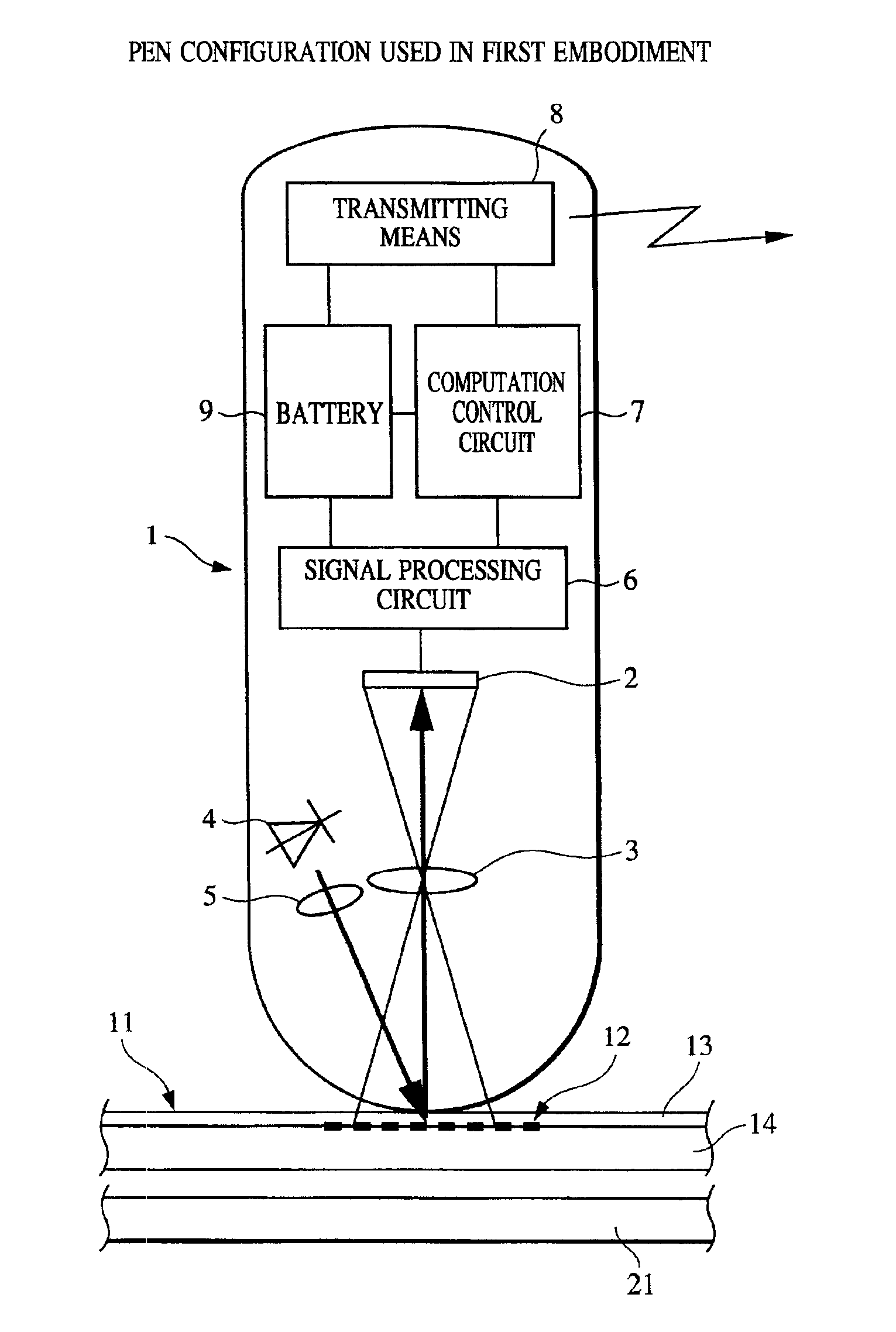
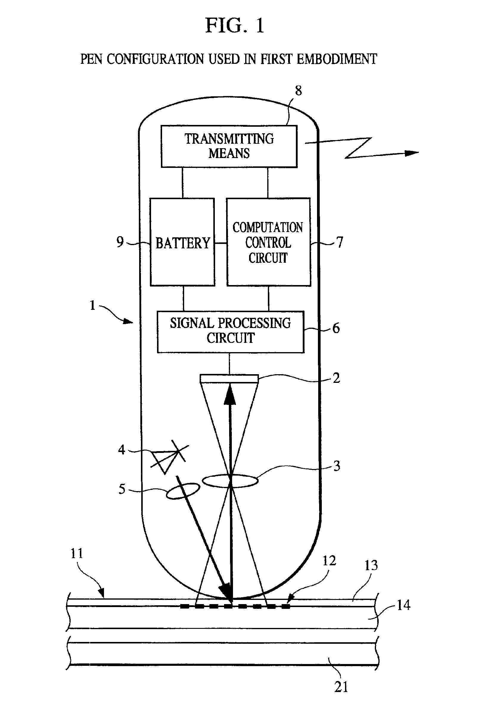
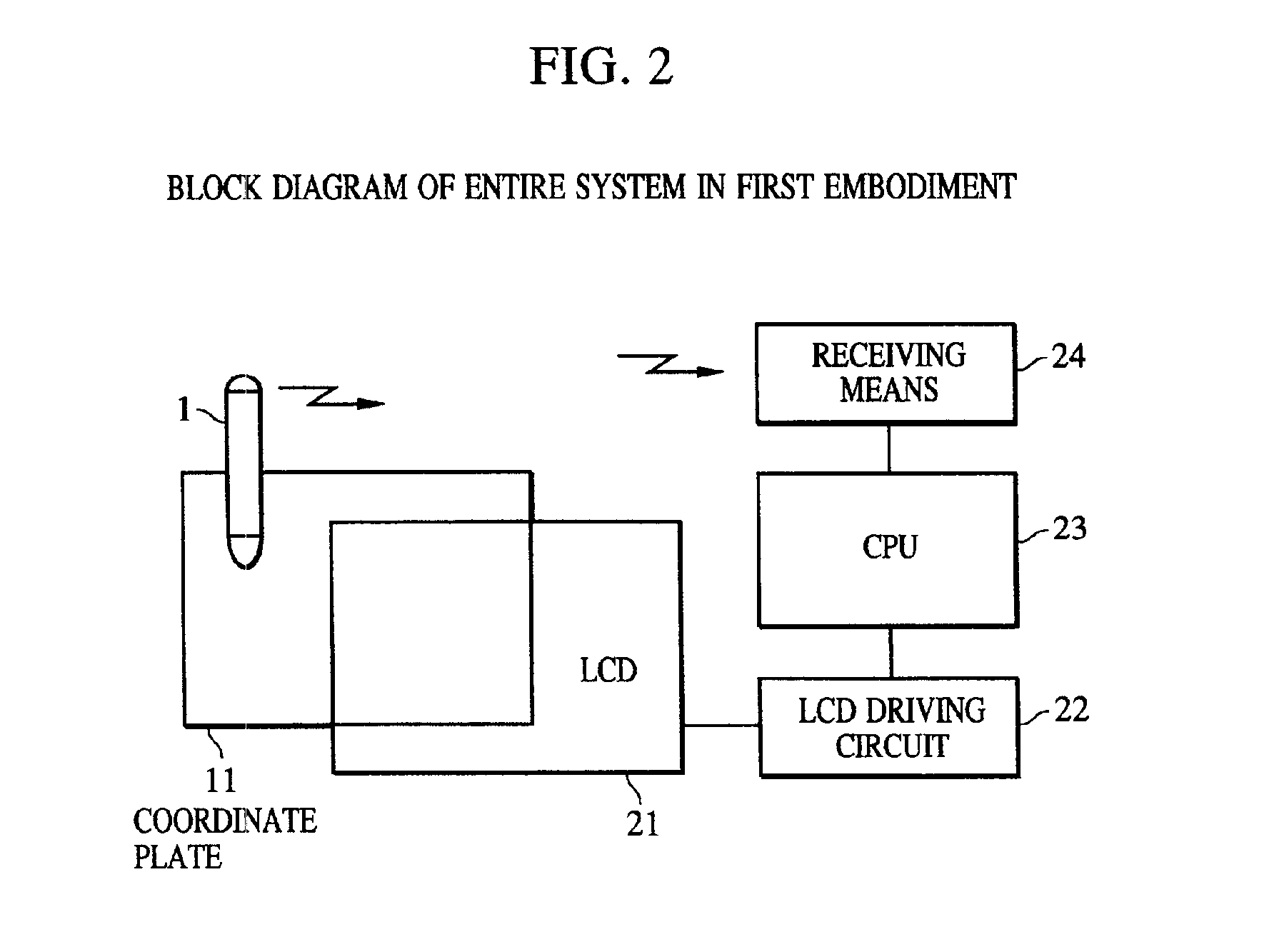
[0044]FIG. 1 is a block diagram showing an input indicator (a pen 1) for use in a coordinate input-output apparatus according to a first embodiment; FIG. 2 is a block diagram showing a system configuration of the entire coordinate input-output apparatus according to the first embodiment.

[0045]First, the entire system configuration will be described. In FIG. 2, an input-output integrated type liquid crystal display (LCD) 21, having a coordinate plate 11 having coded coordinate information recorded thereon laid at the front face, displays desired images by an LCD driving circuit 22 based on the indication from a CPU 23. The pen 1 detects the coordinate information so as to transmit coordinate data to receiving means 24 connected to the CPU 23. The CPU 23 carries out predetermined processing based on the result received by the receiving means 24. In the processing, a menu of commands of a position corresponding to the coordinate data of a point input by the pen 1 is executed, for examp...

second embodiment

[0079]A coordinate input-output apparatus according to a second embodiment will be described with reference to FIGS. 7 and 8. The structure and operation of the pen 1, which is the input indicator, are the same as those in the first embodiment, so that description thereof is omitted. Like reference characters designate like portions having functions common to those of the first and second embodiments. In the embodiment, because of the difference from the first embodiment in the structures of the coordinate plate and the dot array, these points will be mainly described.

[0080]FIG. 7 is a schematic sectional view of a coordinate plate 31 used in the embodiment. According to the embodiment, the coordinate plate 31 also serves as an upper glass plate 21a of the LCD 21. That is, the coordinate plate 31 is formed so that the film 13 is bonded on the top surface of the upper glass plate 21a by using a surface having a dot array 32 formed thereon as the laminating surface. By the structure, ...


PUM


Abstract

A coordinate input apparatus and a coordinate inputting method are provided, in which any influence on display images by coordinate information recorded on a coordinate plate can be extremely reduced and excellent operation of input indication is enabled without being disturbed by the coordinate information. A coordinate input apparatus includes a coordinate plate having plural pieces of coordinate information recorded thereon and a pen, or input-indicator, for indicating a desired position of the coordinate plate so as to detect coordinate information in the vicinity of the position and for indicating a position to be input. Coordinate values are determined from the coordinate information detected by the input-indicator so as to determine a coordinate value of the coordinate in the position to be input on the basis of the coordinate values and to input the coordinate value.

Description

BACKGROUND OF THE INVENTION[0001]1. Field of the Invention[0002]The present invention relates to a coordinate input apparatus and a coordinate input-output apparatus in which an input screen is indicated by an input indicator such as a pen and a mouse so as to detect a positional coordinate indicated by the input indicator to be output to a personal computer and the like.[0003]2. Description of the Related Art[0004]Various types of conventional coordinate input apparatus are known, which are classified by a detection principle based on a physical phenomenon for detecting a position of the input indicator. As are also classified in the International Patents Classification (IPC), such main types are tablets as a resistance tablet, a magnetic coupling tablet, a capacitive coupling tablet, an optical coupling tablet, and an acoustic vibration tablet. The detail description of each type is omitted because the resistance tablet is disclosed in Japanese Patent Laid-Open No. 5-53715; the ma...

Claims


Application Information

Patent Timeline
Patent Type & Authority Patents(United States)
IPC IPC(8): G06F3/033G06F3/042G06F3/03G06F3/041
CPCG06F3/0317G06F3/0321
Inventor YANAGISAWA, RYOZOSATO, HAJIME
Owner CANON KK
Why Eureka
Try Eureka