
Ball mold

Inactive Publication Date: 2006-02-23
UNIVERSAL SPORTING GOODS THAI
View PDF3 Cites 3 Cited by
  • Summary
  • Abstract
  • Description
  • Claims
  • Application Information

AI Technical Summary

Benefits of technology

[0008] The main objective of the invention is to provide a ball mold that simplifies manufacturing processes of making a ball with two different surfaces.

Problems solved by technology

Additionally, the attached artificial leather causes bulges on the surface of the ball so that the ball with two different surfaces is uneven which may have a serious effect on the ball's behavior.

Method used


Image

  • Ball mold
  • Ball mold
  • Ball mold

Examples


Embodiment Construction

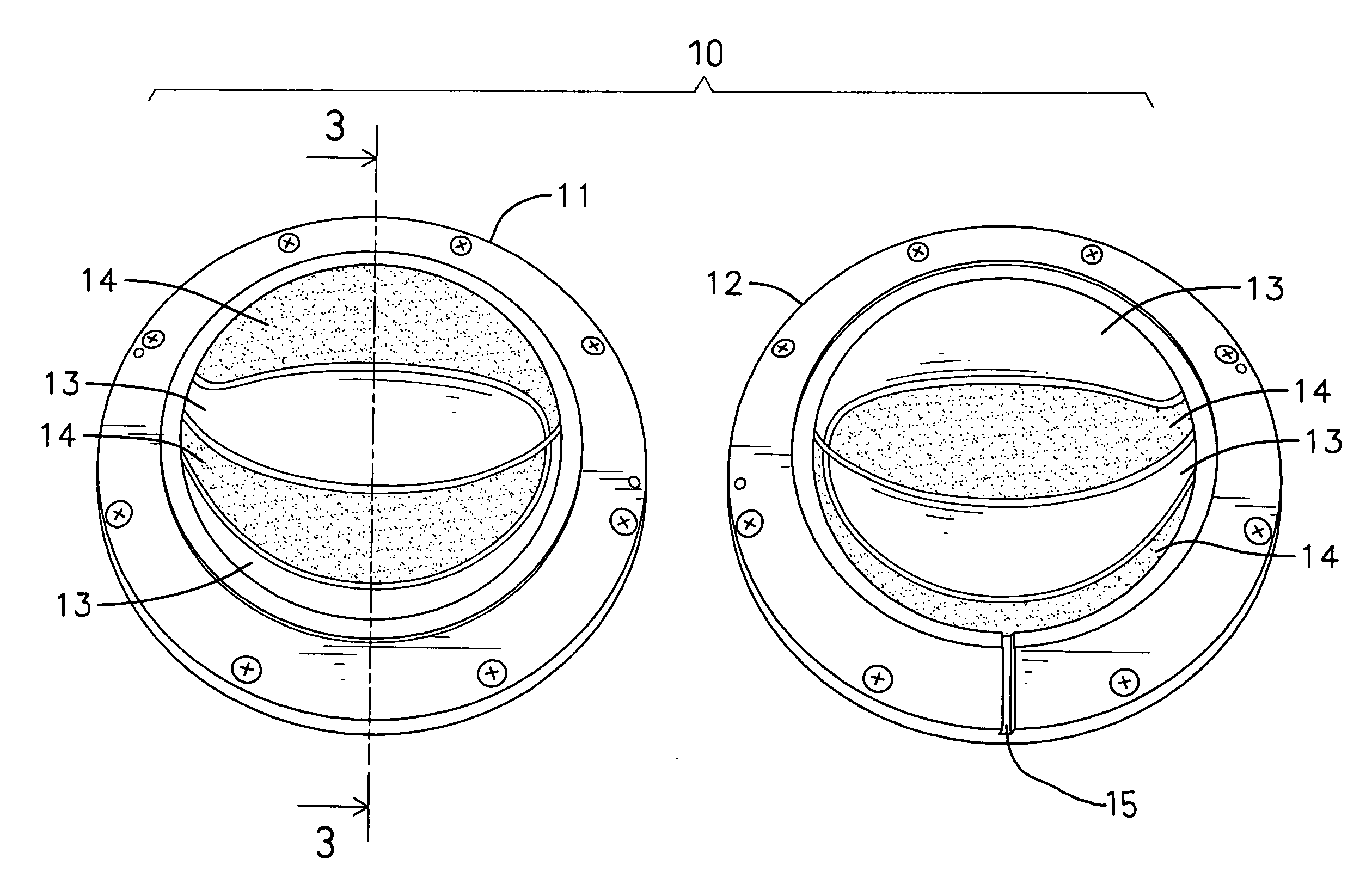
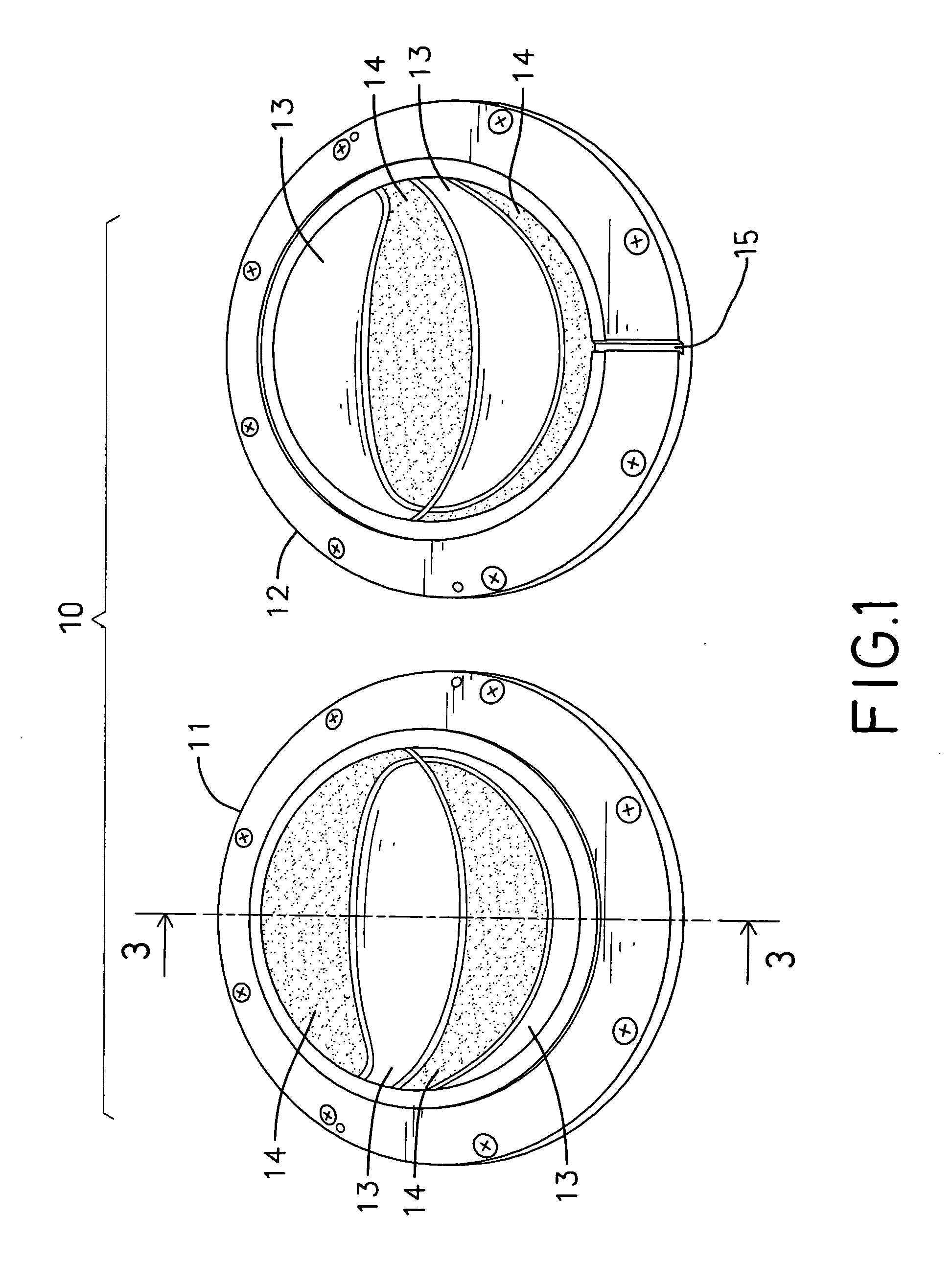
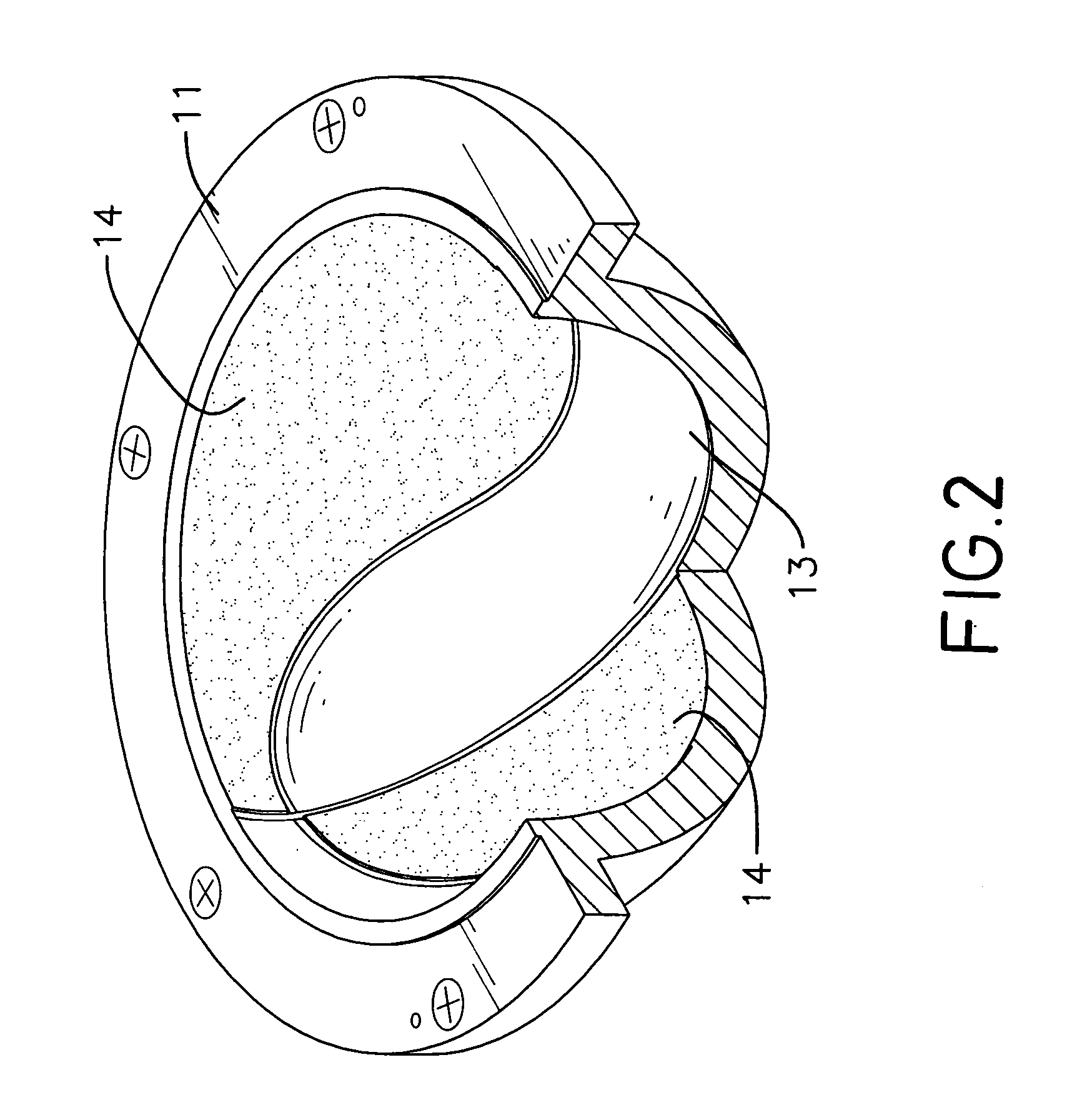
[0015] A ball mold in accordance with the present invention comprises two half bodies, two hemispherical cavities respectively defined in the two half bodies and corresponding with each other to perform a ball-shaped interior. Each of the two half bodies has an inner surface and at least one smooth area and at least one rough area; both areas are defined in the inner surface. Preferably, each smooth area has a gouged depth deeper than that of the rough area. Therefore, a ball molded by the ball mold has rough elevated portions corresponding to the rough areas on the ball mold and smooth recesses corresponding to the smooth areas on the ball mold. The ball only needs to be attached with pieces of artificial leather inside smooth recesses to be flush with the rough elevated portions. Thus, the ball with two different surfaces is achieved in a simplified way without thermal pressing.

[0016] With reference to FIG. 1 to 3, a preferred embodiment of the ball mold (10) in the present appli...


PUM

PropertyMeasurementUnit
Depthaaaaaaaaaa

Abstract

A ball mold is composed of two half bodies and two hemispherical cavities respectively defined in the two half bodies to correspondingly match with each other to perform a ball-shaped interior inside the ball mold. Each of the two half bodies has an inner surface, at least one smooth area and at least one rough area; both areas are defined in the inner surface. Preferably, the smooth area has a gouged depth deeper than that of the rough area. Therefore, a ball molded by the ball mold has rough elevated portions corresponding to the rough areas on the ball mold and smooth recesses corresponding to the smooth areas on the ball mold. The ball only needs to be attached with pieces of artificial leather inside smooth recesses to be flush with the rough elevated portions. Thereby, the ball with two different surfaces is achieved in a convenient way without thermal pressing.

Description

BACKGROUND OF THE INVENTION [0001] 1. Field of the Invention [0002] The present invention relates to a ball mold, and more particularly a ball mold that conveniently manufactures a ball having two different surfaces in a simplified process. [0003] 2. Description of Related Art [0004] Inflatable balls, such as a basketball or a volleyball, are basically composed of multiple layers including an inner body with an interior, a fabric layer, an intermediate layer and a coat. When manufacturing the inflatable ball, a string surrounds the inner body to form the fabric layer to protect the inner body. The inner body with the fabric layer is placed into a conventional mold. Then, vulcanized rubber liquid is poured into the conventional mold to surround the fabric layer to form the intermediate layer. An inlet nozzle penetrates through the intermediate layer and the fabric layer to communicate with the interior of the inner body. After the intermediate layer has solidified, the outer peripher...

Claims


Application Information

Patent Timeline
IPC IPC(8): B29C33/42
CPCB29C33/424B29L2031/54B29C45/372B29C45/14819
Inventor SU, KUANG-HUILEI, TSE-HUI
Owner UNIVERSAL SPORTING GOODS THAI
Learn More