Coin changing machine

Inactive Publication Date: 2006-02-23
JAPAN CASH MASCH CO LTD
View PDF2 Cites 13 Cited by
  • Summary
  • Abstract
  • Description
  • Claims
  • Application Information

AI Technical Summary

Benefits of technology

[0015] The ejection control member including the stopper adjacent to the ejection belt makes it possible to control the coin-storing operation and the stored-coin ejecting operation only by varying the distance betw

Problems solved by technology

However, the use of above vertically-long stacking hoppers causes a problem about increase in vertical length or thickness of the coin change dispenser, which hinders downsizing thereof.
While it can be contemplated to lay down each of the stacking hoppers and allow coins dropped on the upstream end of the s

Method used


Image

  • Coin changing machine
  • Coin changing machine
  • Coin changing machine

Examples


Embodiment Construction

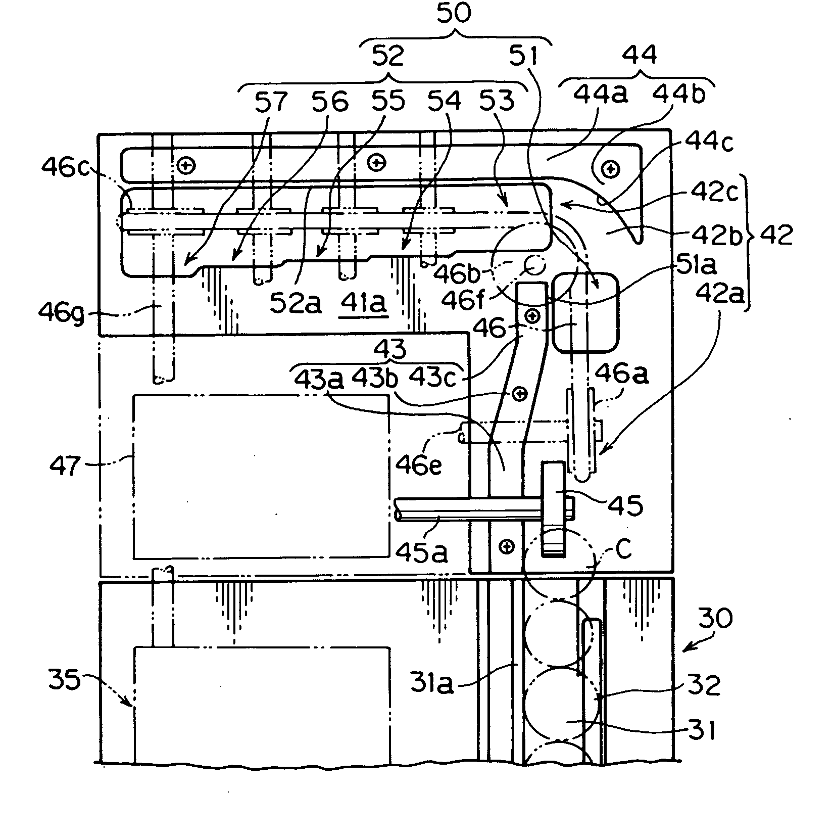
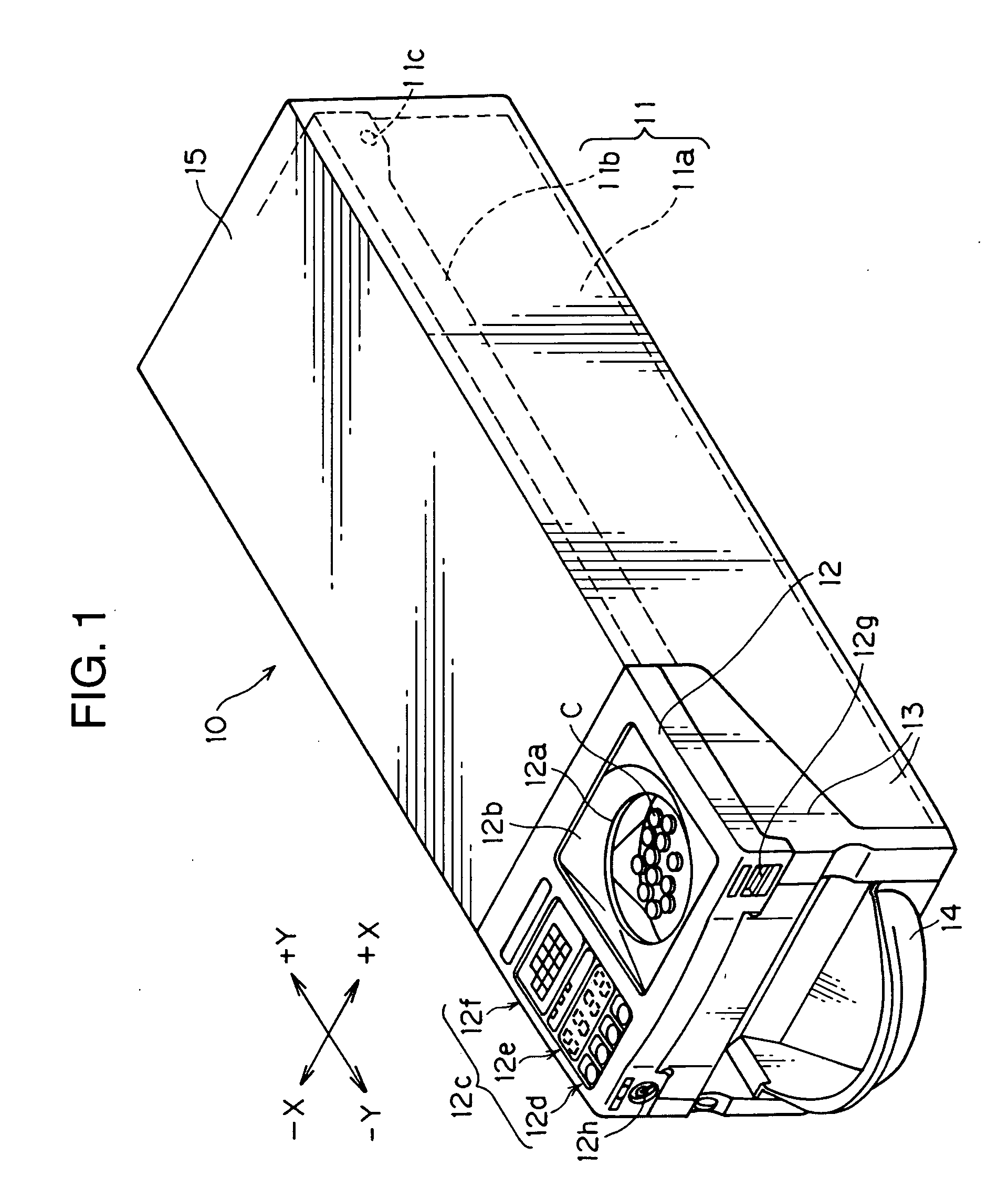
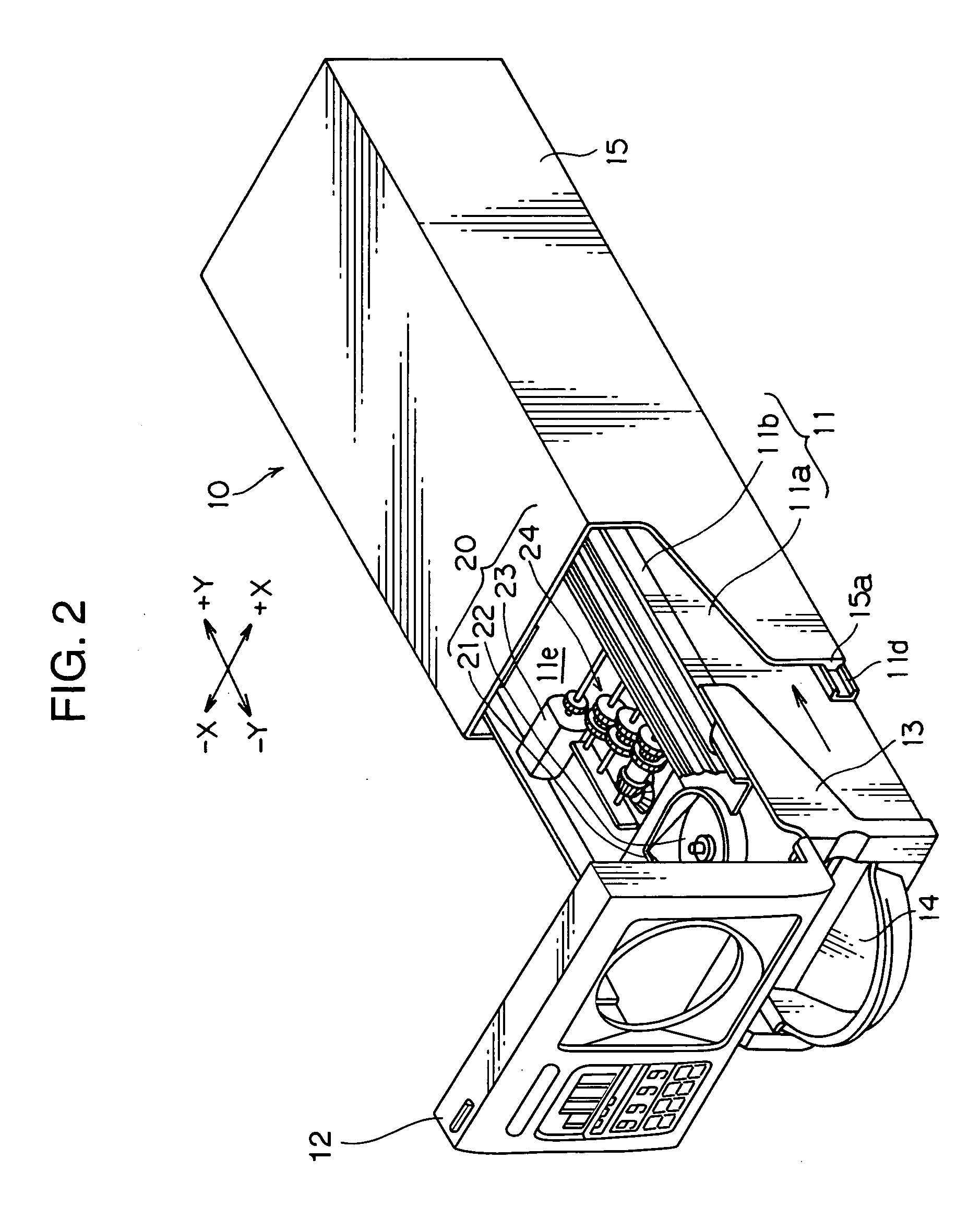
[0031]FIG. 1 is an external perspective view showing a coin change dispenser according to one embodiment of the present invention. The X-X direction and Y-Y direction in FIG. 1 are hereinafter referred to as “width direction” and “longitudinal direction”, respectively. In particular, the −X direction, +X direction, −Y direction and +Y direction are hereinafter referred to as “leftward”, rightward”, “frontward” and “rearward”, respectively.

[0032] As shown in this figure, the coin change dispenser 10 is designed to have a rectangular parallelepiped-shaped external appearance with a long length, and formed by mounting various devices in a frame 11 having a box or pit shape in top plan view. The frame 11 comprises a basic frame 11a serving as a structural base of the coin change dispenser 10, and an openable frame 11b superimposed on an upper portion of the basic frame 11a, and adapted to be swingable around a connecting shaft 11c provided at the rear end of the basic frame 11a to exte...


PUM


Abstract

Disclosed is a coin change which comprises a coin sort section 50 for sorting coins C discharged from an input hopper 21, and a coin storage section 60 for storing the coins C sorted by the coin sort section 50 on a coin type by type basis. The coin storage section 60 includes a plurality of coin storage grooves 63 provided respectively to the plural coin types and disposed parallel to each other. Each of the coin storage grooves has a width dimension slightly greater than the diameter of a corresponding one of the types of coins and extends approximately horizontally. The coin storage section 60 also includes a stacking belt 65 disposed along the base of each of the coin storage grooves to extend in the longitudinal direction of the coin storage grooves, and a stopper member disposed at the downstream end of each of the coin storage grooves and adapted to be moved between a coin-passing-enabling position of allowing one or more of the coins C to pass therethrough and a stack position preventing the passing of the coins C so as to allow the subsequent coins C to be stacked on each other

Description

TECHNICAL FIELD [0001] The present invention relates to a coin change dispenser for use in ejecting a change in coin. BACKGROUND ART [0002] Heretofore, there has been known a coin change dispenser for use in ejecting a change in coin. This coin change dispenser is designed to transfer toward a coin passage plural types of coins put in an input hopper, to sort the coins into their coin types through a plurality of sorting holes located downstream of the coin passage, and to store the sorted coins in a storage section on a coin type by type basis. Each of the plurality of sorting holes is formed to have a diametral dimension conforming to that of a corresponding one of the types of coins. These sorting holes are serially disposed in ascending order of diametral dimension. The coins transferred to the respective positions of the sorting holes are dropped down through corresponding ones of the sorting holes, and stored in a plurality of storage hoppers provided respectively to the plura...

Claims


Application Information

Patent Timeline
IPC IPC(8): G07D1/00G07D3/00G07D1/02G07D1/06G07D3/02G07D3/04G07D9/00G07D9/06G07F5/24
CPCG07D1/00G07D1/02G07F5/24G07D3/04G07D9/00G07D3/02G07D1/06G07D9/008
Inventor NISHIMURA, KAZUYAYAMAUCHI, HIROAKITAKASHIMA, NOBUO
Owner JAPAN CASH MASCH CO LTD
Why Eureka
Try Eureka