
Systems and methods for medical device a dvancement and rotation

a medical device and system technology, applied in the field of systems and methods for medical devices a dvancement and rotation, can solve the problems of difficult advancing of one elongated medical device within and/or next to another elongated device, and achieve the effect of improving the dvancement and rotation rate of one elongated medical devi

Active Publication Date: 2006-02-23
STEREOTAXIS
View PDF12 Cites 281 Cited by
  • Summary
  • Abstract
  • Description
  • Claims
  • Application Information

AI Technical Summary

Benefits of technology

[0006] In many interventional medical procedures multiple devices are inserted into a patient's anatomy for diagnosis and therapy. The present invention is directed to a motion control mechanism for moving at least one elongate medical device and addresses the need for computer control of the motion of multiple devices, either independently or in tandem, when such procedures are performed by robotic or other remotely actuated means. The motion control mechanism can perform the functions of device advancement and retraction, or axial rotation of at least one of the devices, or any combination of these motions. A computer can control these motions in such a manner as to be able to produce a discrete or continuous sequence of movements of the various devices in any combination, if so desired in the medical procedure. An example of such a sequence in interventional medical procedures is a doddering motion comprising a rapidly alternating sequence of small advancements and retractions, which could be one method of finding a pathway through an occluded or partially occluded vessel in a patient, where the device could have a straight, curved, or actuated distal tip.

Problems solved by technology

However, the physician still must manually advance the device once the distal end of the device is the desired orientation.
Advancing one elongate medical device within and / or next to another elongate device, however, is frequently made difficult by a number of factors, including but not limited to the lengths and frictional characteristics of the devices.

Method used


Image

  • Systems and methods for medical device a dvancement and rotation
  • Systems and methods for medical device a dvancement and rotation
  • Systems and methods for medical device a dvancement and rotation

Examples


Embodiment Construction

[0043] The following description of the preferred embodiment(s) is merely exemplary in nature and is in no way intended to limit the invention, its application, or uses. Reference is made to U.S. patent application Ser. No. 10 / 138,710 filed on May 3, 2002, the disclosure of which is incorporated herein by reference in its entirety.

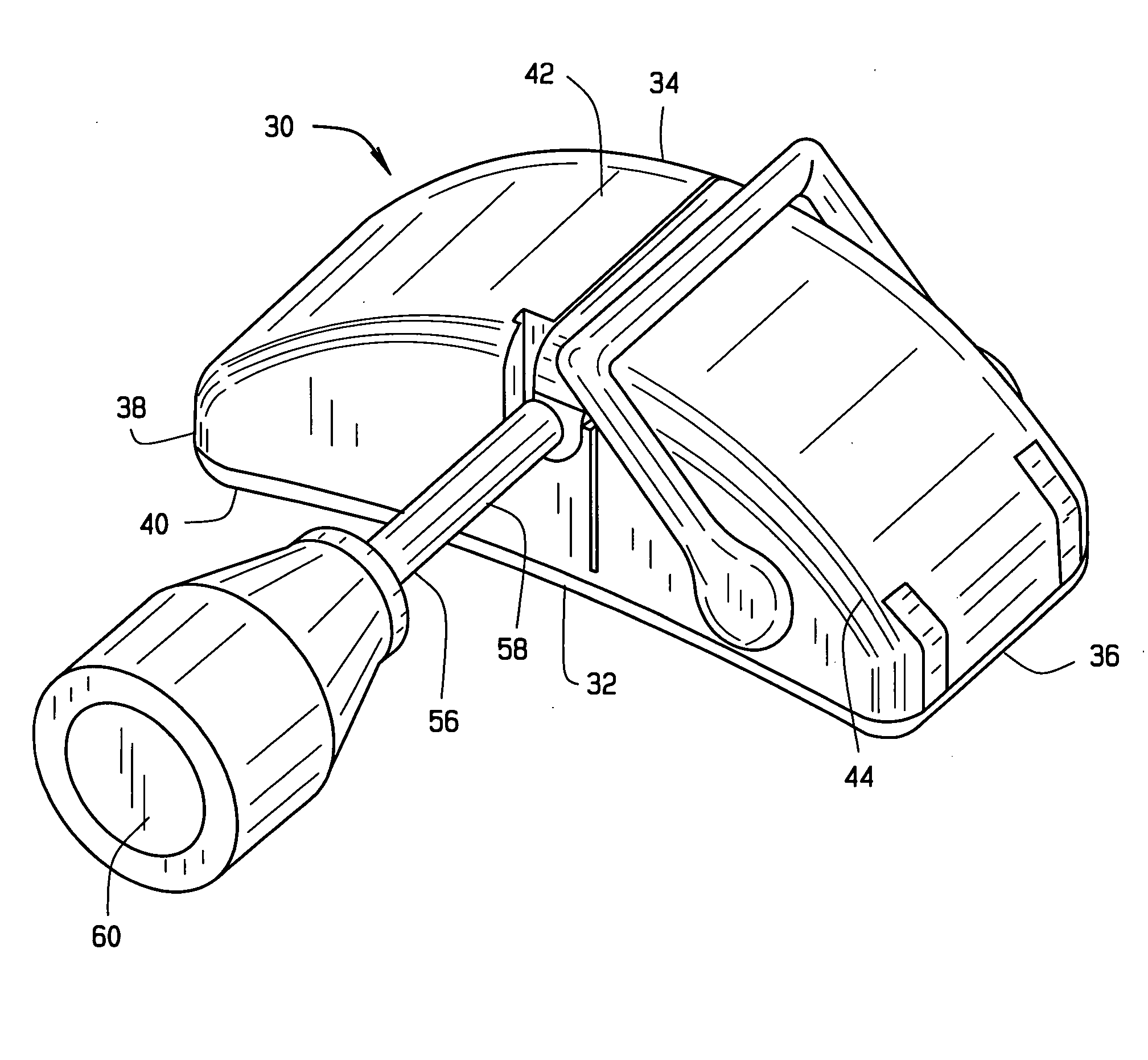
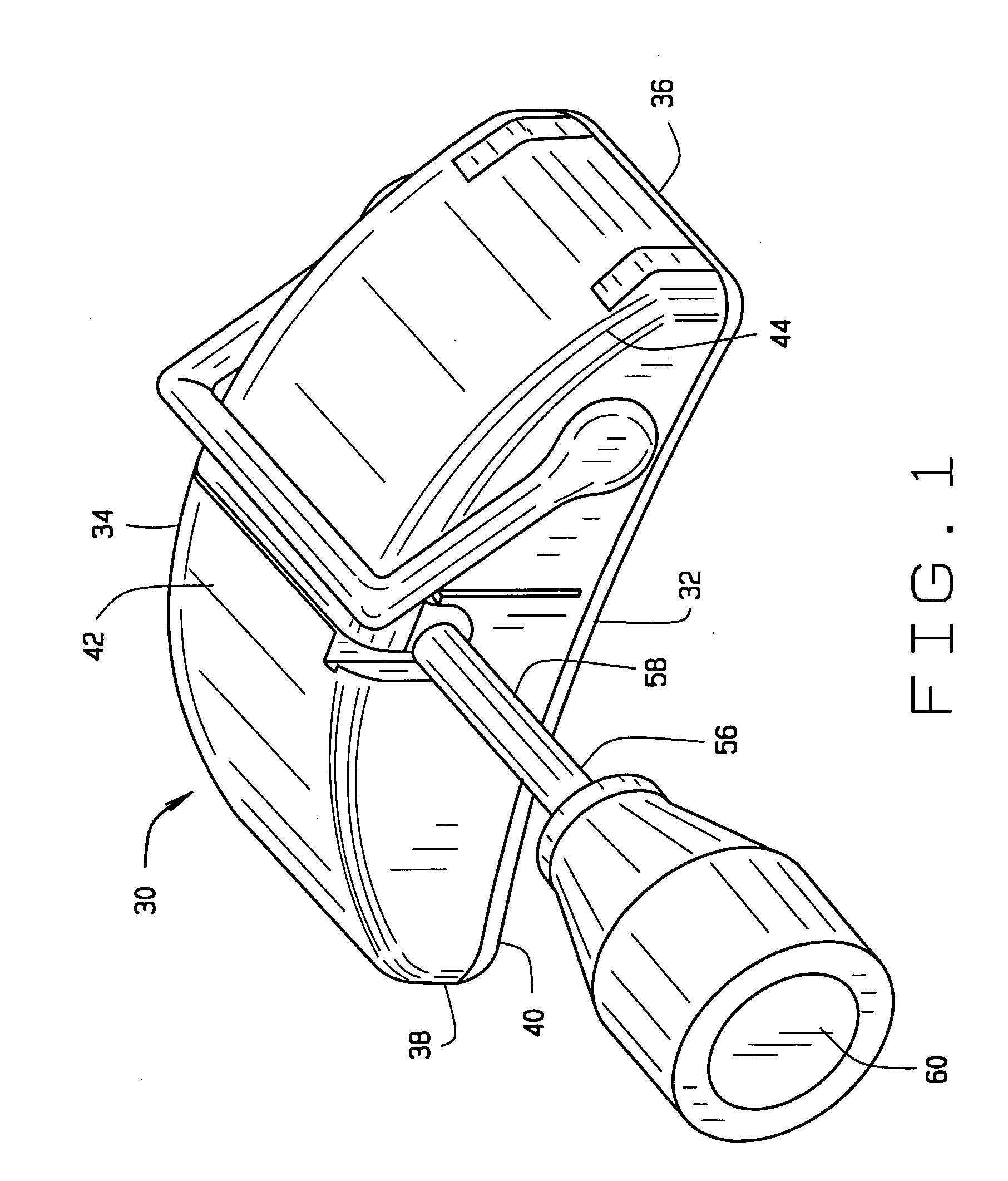
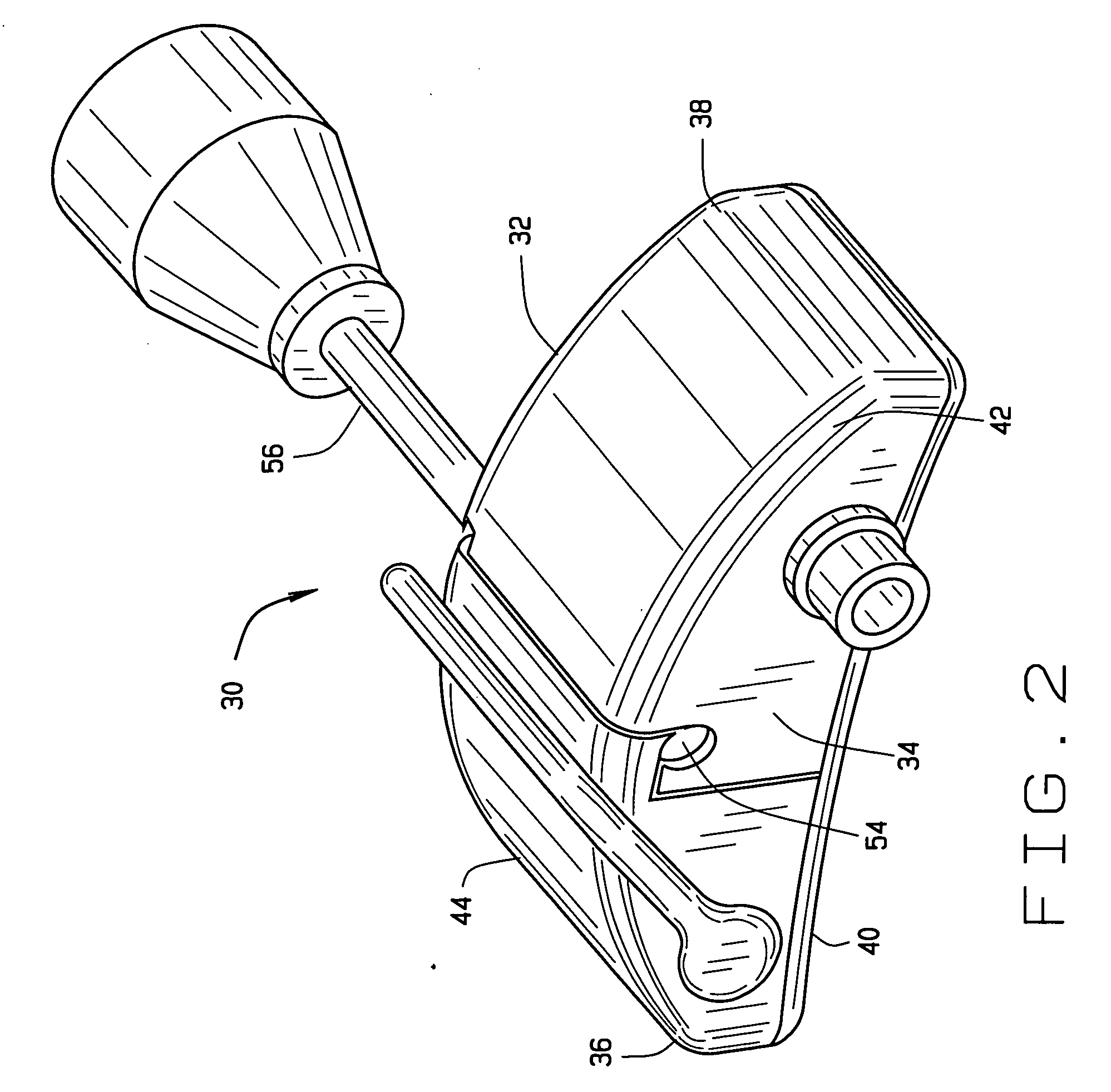
[0044] A first embodiment of a drive unit or advancer constructed according to the principles of this invention is indicated generally as 10 in FIGS. 1 through 7. The drive unit or advancer 10 is adapted for moving at least one elongate medical device such as a catheter and / or guide wire in the body of a subject. The advancer 30 is preferably small: for example in this first preferred embodiment it is about 2.6 inches long, about 1.1 inches wide (the longitudinal direction), and 1 inch high. The advancer 30 is preferably sterile, and is preferably sufficiently inexpensive to be disposable. The advancer 30 can be positioned close to the site where an elong...


PUM


Abstract

A system for moving an elongate medical device has at least one drive element for engaging and moving an elongate medical device. Various embodiments provide for moving the separate inner and outer elements of a telescoping medical device. Some systems also provide for the rotation of a rotatable distal element on a rotatable medical device or the rotation of extension element in a telescoping medical device.

Description

CROSS-REFERENCE TO RELATED APPLICATIONS [0001] This application is a continuation-in-part of U.S. patent application Ser. No. 10 / 138,710 filed on May 3, 2002, which claims priority to U.S. Provisional Patent Application No. 60 / 288,879, filed May 6, 2001. The disclosures of the above applications are incorporated herein by reference in their entirety.BACKGROUND OF THE INVENTION [0002] A variety of techniques are currently available to physicians for controlling elongate medical devices such as catheters, endoscopes and other surgical tools within a patient. For example, magnetic steering techniques provide computer-assisted control of a catheter tip while allowing an operating physician to remain outside the operating room x-ray field. Thus the physician, freed from having to manually steer the catheter tip. [0003] However, the physician still must manually advance the device once the distal end of the device is the desired orientation. A number of medical procedures call for more th...

Claims


Application Information

Patent Timeline
Patent Type & Authority Applications(United States)
IPC IPC(8): A61M31/00A61M25/00A61B5/00A61B17/22A61M25/01
CPCA61B1/00133A61B1/01A61B17/22A61B17/3403A61M25/0113A61B2017/22075A61B2017/3409A61B2019/268A61B19/26A61B90/50A61B2090/571
Inventor FERRY, STEVEN J.FINNEY, JENNIFER R.HABEGER, CAMHACKENMUELLER, VINCENTHALL, ANDREW F.HOUGE, REED A.KLIMEK, SCOTT G.PIKUS, MICHAEL J.
Owner STEREOTAXIS
Learn More