

Knee pad construction
a knee pad and construction technology, applied in the field of knee pads, can solve the problem that the knee pads do not compensate for the distinction between the knee pads thus are typically not suitable for left and right knees, so as to facilitate the movement of gel material and facilitate the maintenance of the knee pad construction
- Summary
- Abstract
- Description
- Claims
- Application Information
AI Technical Summary
Benefits of technology
Problems solved by technology
Method used
Image

Examples
Embodiment Construction
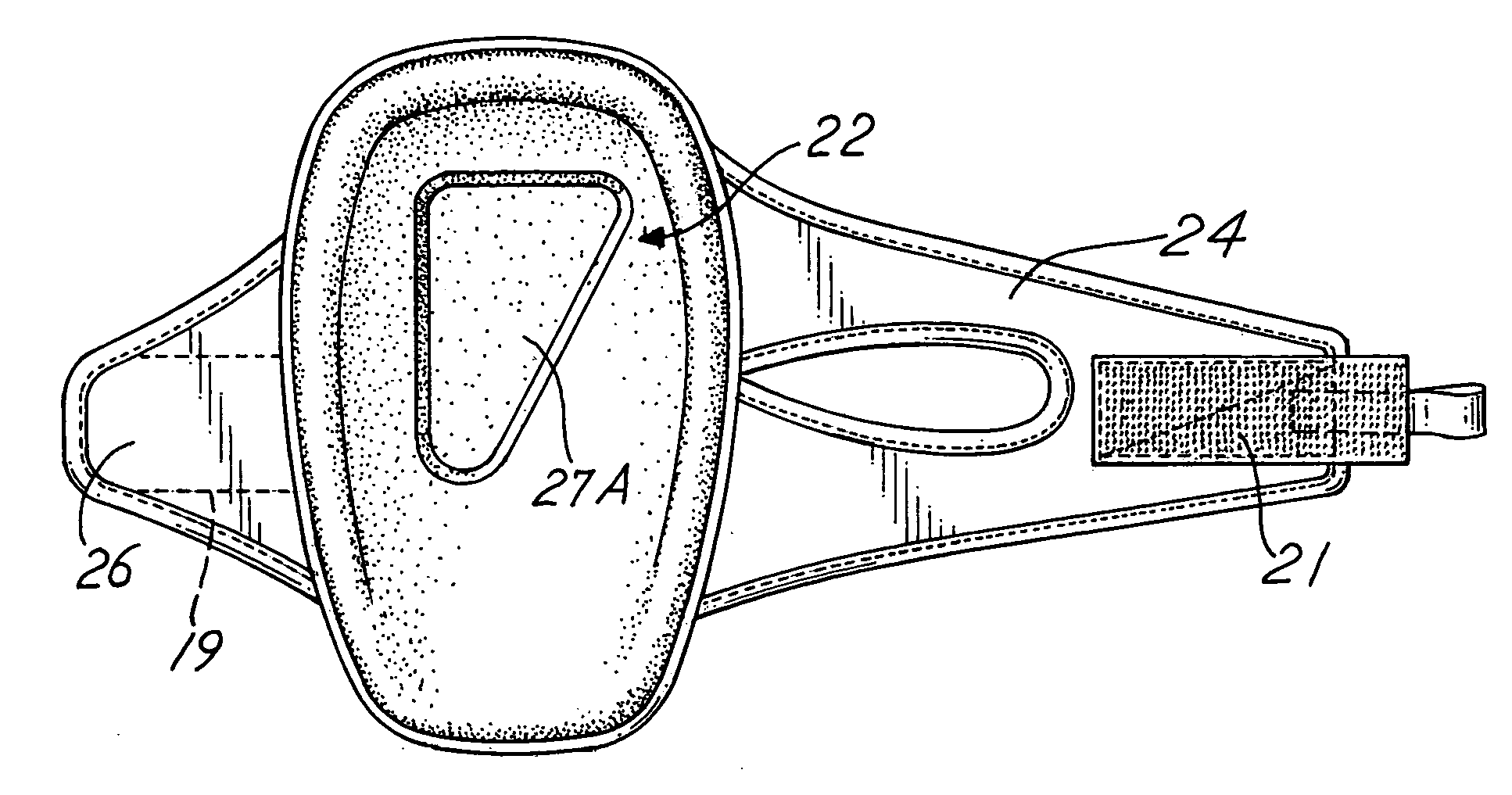
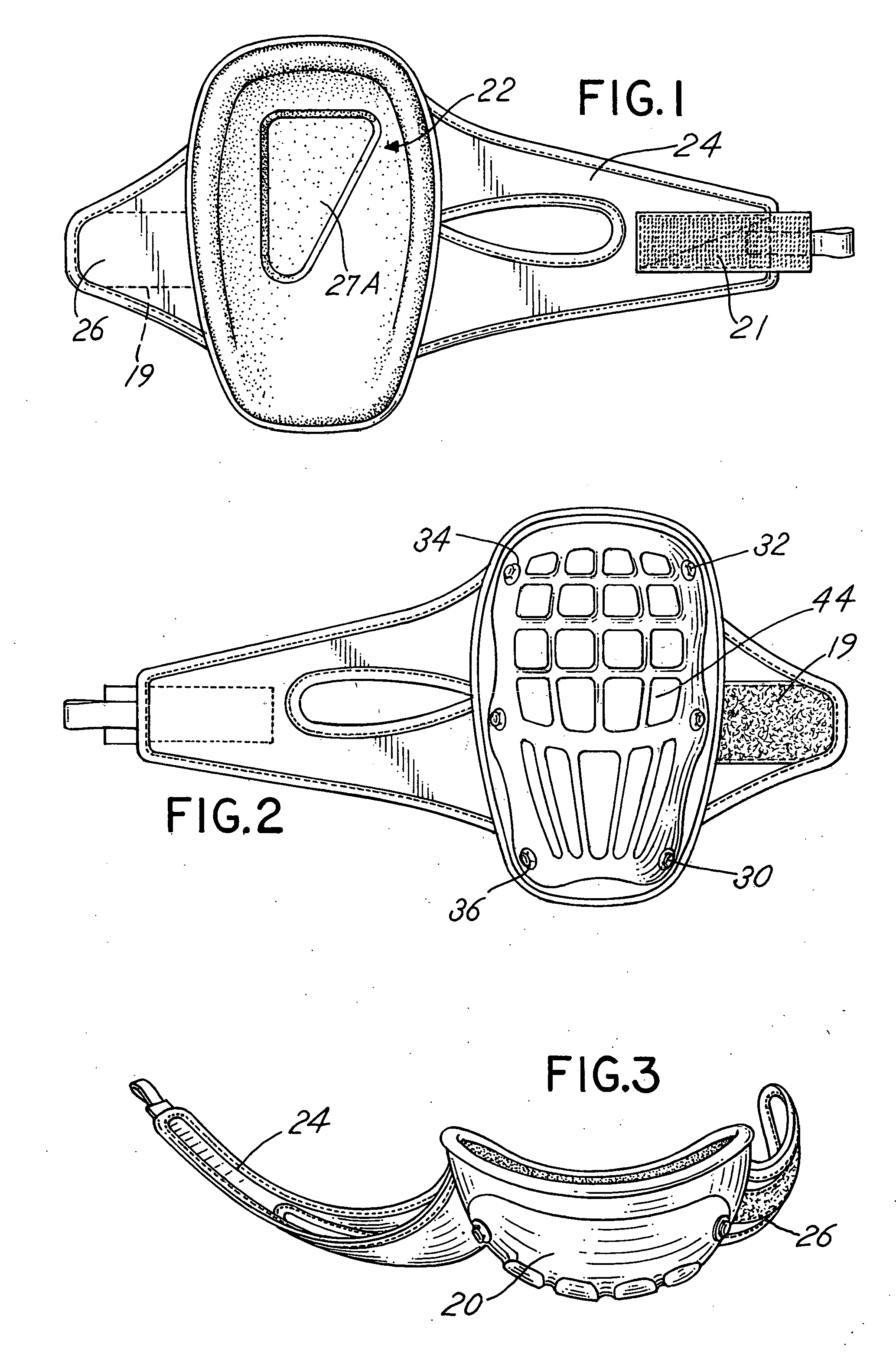
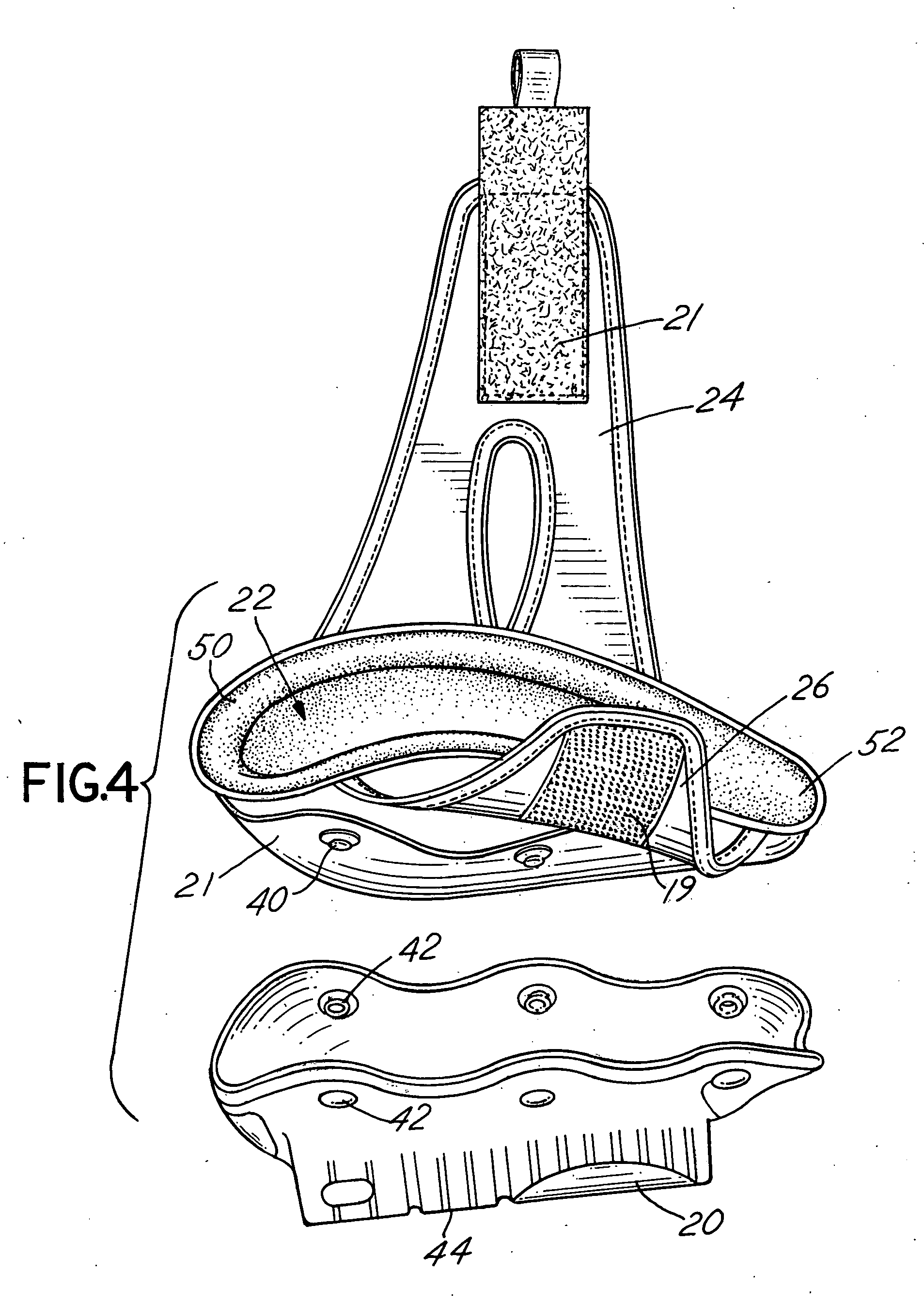
[0037] Referring to the figures, and in particular FIG. 4, a preferred embodiment of a knee pad assembly of the invention is generally comprised of two basic components. The first component is an outer shell or casing or case 20. The second basic component is an inner, shaped cushion element, pad assembly or core 22 (See FIGS. 1-3) which includes a strap construction, for example, strap 24 and compatible strap attachment 26. The casing or shell or case 20 is affixed to the shaped cushion element 22 to provide a hard outer layer or shell which is designed to engage against a surface, such as a floor. The hard outer casing or shell 20 is typically attached by means of snaps, for example, snaps 30, 32, 34 and 36 to the interior shaped cushion element 22. That is, an external convex surface 21 of the cushion element 22 includes snap members 40 compatible with snap members such as snap member 42 of shell 20, for attachment of the shell or casing or outer member 20 to the cushion element ...
PUM
 Abstract
Description
Claims
Application Information