Apparatus for dispensing flowable contents of a collapsible tube

a technology of flowable contents and collapsible tubes, which is applied in the direction of flexible containers, pliable tubular containers, packaging, etc., can solve the problems of difficulty, if not impossible, in emptying the contents of some tubes, and not being completely satisfactory in ease of handling, operation, durability, maintenance and/or cost, etc., and achieve uniform thickness

Inactive Publication Date: 2006-03-02
BURRELL WILLIAM E
View PDF21 Cites 13 Cited by
  • Summary
  • Abstract
  • Description
  • Claims
  • Application Information

AI Technical Summary

Benefits of technology

[0002] A handheld device in the form of a squeezer for emptying contents for a tube is made of a stiff, but resilient, segment of material, preferably plastic, having a uniform thickness. The squeezer has a lateral width slightly greater than the collapsed width of the tube for which it is designed and a length greater than its width. The segment is bent upwardly at about its midpoint about 165 degrees to form a loop and then is bent upwardly to form a rounded laterally extending tube gripping ridge or dimple. This results in a flat bottom plate connected by the loop to a slightly concave top plate disposed at about a 17 degree angle to the bottom plate. A laterally extending slot is formed in the loop just above the level of the bottom plate. The slot has a lateral dimension slightly greater than the width of tube in a flattened state and a vertical dimension slightly greater than the collapsed thickness of the tube. The lateral dimension of the slot is less than the lateral dimension of the loop thereby leaving narrow portions of the loop at opposite lateral ends of the slot which serve as a live hinge.

Problems solved by technology

It is difficult, if not impossible, to empty the contents of some tubes by hand squeezing the tube.
Numerous devices have been proposed for assisting a person in dispensing the flowable contents from a collapsible tube; however, they have not proven entirely satisfactory as to ease of handling, operation, durability, maintenance and / or cost.

Method used


Image

  • Apparatus for dispensing flowable contents of a collapsible tube
  • Apparatus for dispensing flowable contents of a collapsible tube
  • Apparatus for dispensing flowable contents of a collapsible tube

Examples


Embodiment Construction

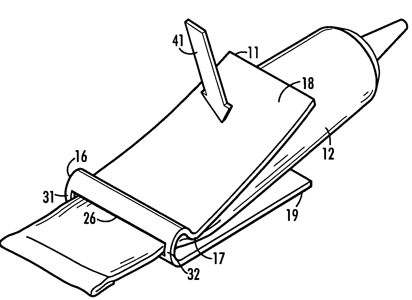
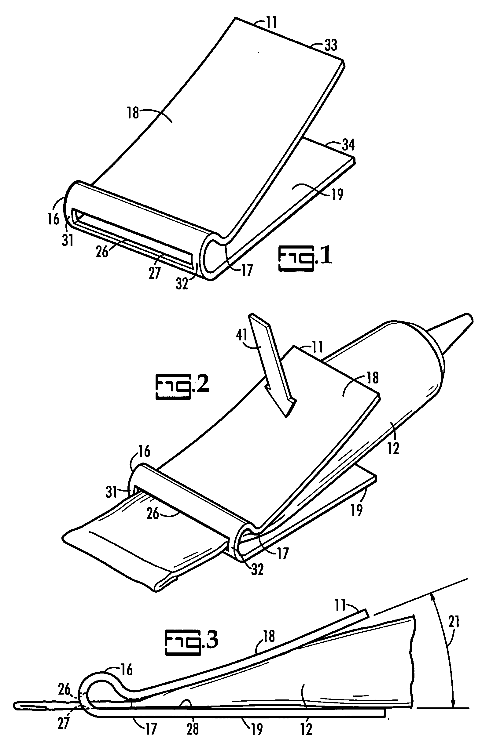
[0009]FIGS. 1 through 3 show the hand held device or tube squeezer 11 for emptying the contents of a collapsible tube 12 which may contain any one of a wide variety of industrial products such as caulking, grouting, sealants or household products such as toothpaste. The tube squeezer is made of an elongated segment of thin flat resilient material of uniform thickness, preferably thermo plastic, which is bent over on itself about 165 degrees at near the midpoint of its length to form a loop 16. The segment is next bent upwardly from the loop to form a downwardly extending dimple 17 and then is bent upwardly a slight amount to present a slightly rounded or concave top plate 18 extending above a flat bottom plate 19 at an acute angle 21 between 10 and 25 degrees preferably about 17 degrees. The downward extending dimple 17 provides a rounded laterally extending tube gripping ridge which grips the tube when the top plate is pivoted downwardly about a live hinge. The width of the tube sq...


PUM


Abstract

A hand held tube squeezer facilitates emptying a tube of its contents. The squeezer has a gripping action on the tube to which it is applied, thus preventing rearward slipping of the squeezer. Top and bottom plates of the squeezer are connected by a loop which has a slot through which a tube extends when it is being emptied. Portions of the loop at opposite ends of the slot function as a line hinge between the top and bottom plates. The squeezer and a roller are packaged in a clear plastic wrap film.

Description

BACKGROUND OF THE INVENTION [0001] A great many materials such as toothpaste, caulk, and the like are packaged in squeeze tubes, which are squeezed from the bottom up. It is difficult, if not impossible, to empty the contents of some tubes by hand squeezing the tube. Numerous devices have been proposed for assisting a person in dispensing the flowable contents from a collapsible tube; however, they have not proven entirely satisfactory as to ease of handling, operation, durability, maintenance and / or cost. There exits a need for an inexpensive durable maintenance free hand held device for compressing flowable material from a tube which is easily applied to and removed from the tube. SUMMARY OF THE INVENTION [0002] A handheld device in the form of a squeezer for emptying contents for a tube is made of a stiff, but resilient, segment of material, preferably plastic, having a uniform thickness. The squeezer has a lateral width slightly greater than the collapsed width of the tube for w...

Claims


Application Information

Patent Timeline
Patent Type & Authority Applications(United States)
IPC IPC(8): B65D35/28
CPCB65D35/28
Inventor BURRELL, WILLIAM E.
Owner BURRELL WILLIAM E
Why Eureka
Try Eureka