RFID tag for instrument handles

Active Publication Date: 2006-03-02
WARSAW ORTHOPEDIC INC
View PDF15 Cites 47 Cited by
  • Summary
  • Abstract
  • Description
  • Claims
  • Application Information

AI Technical Summary

Benefits of technology

[0006] Embodiments of the present invention mitigate or solve the above-identified limitations in known solutions, as well as other unspecified deficiencies in known solutions. A number

Problems solved by technology

In many instances, much of an instrument may not be suitable for application of an RFID tag.
However, many conventional dielectric substrates are impracticable in view of the uses and handling of the instrument.
Similarly, paper- or cardboard-backed RFID tags frequently deteriorate to the point of being useless after frequent handling of an instrument.
Those conventional RFI

Method used


Image

  • RFID tag for instrument handles
  • RFID tag for instrument handles
  • RFID tag for instrument handles

Examples


Embodiment Construction

[0020] The following description is intended to convey a thorough understanding of the present invention by providing a number of specific embodiments and details involving implementing RFID tags in surgical instruments, and in particular to soft-handled instruments. It is understood, however, that the present invention is not limited to these specific embodiments and details, which are exemplary only. It is further understood that one possessing ordinary skill in the art, in light of known systems and methods, would appreciate the use of the invention for its intended purposes and benefits in any number of alternative embodiments, depending upon specific design and other needs.

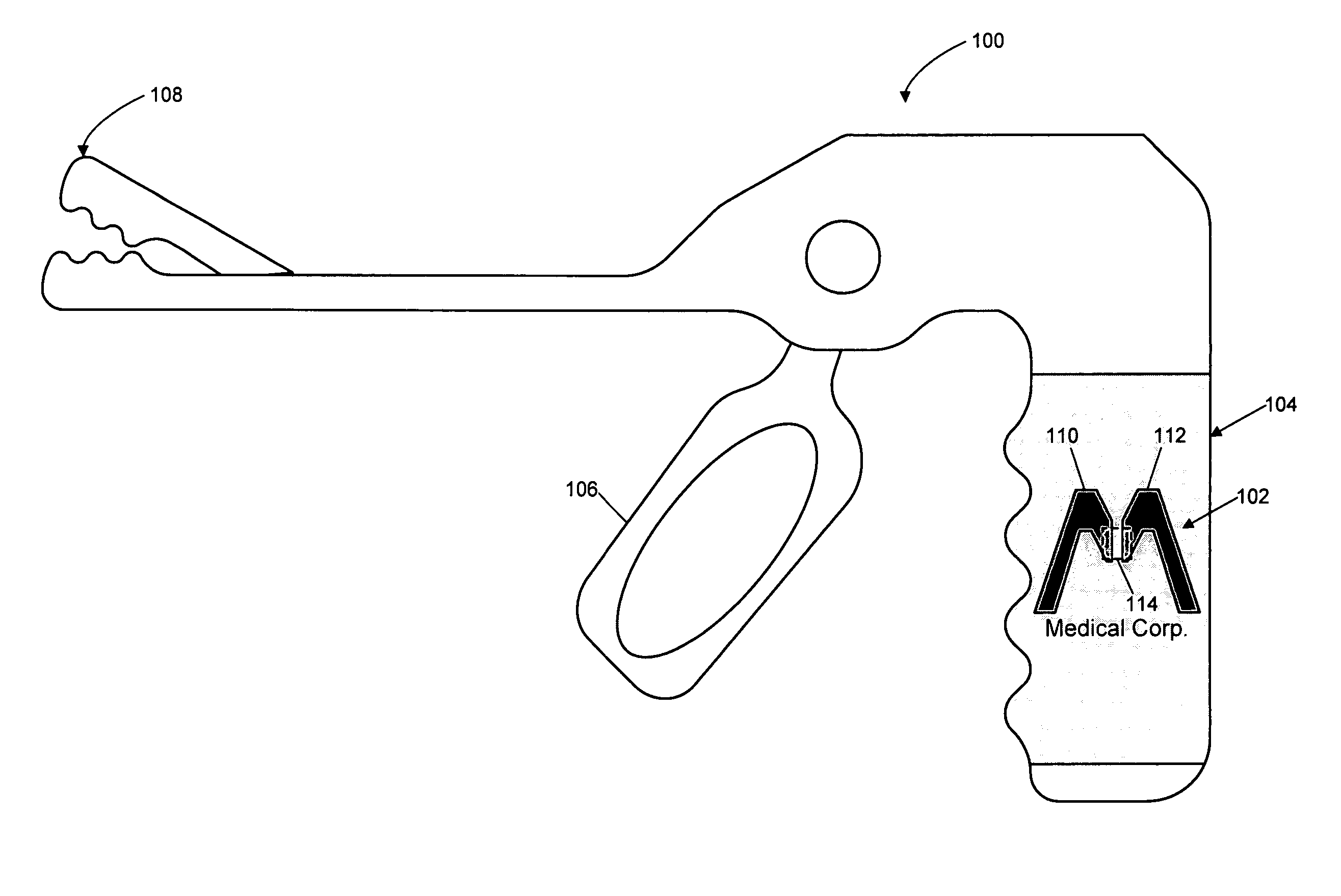
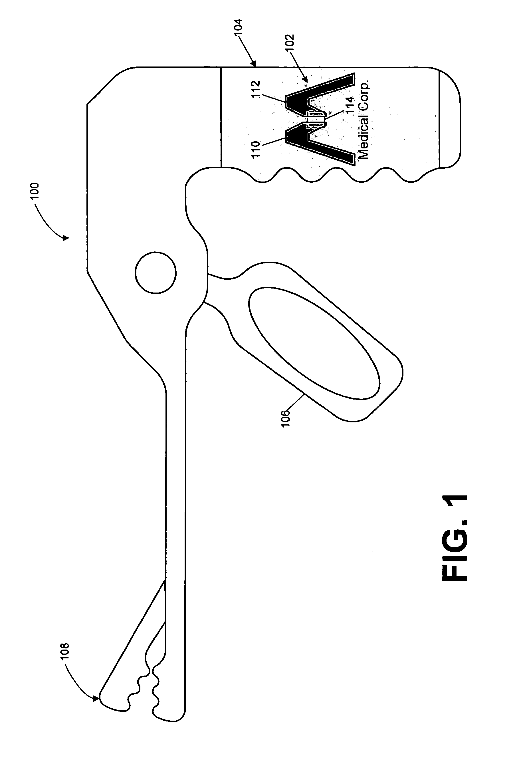
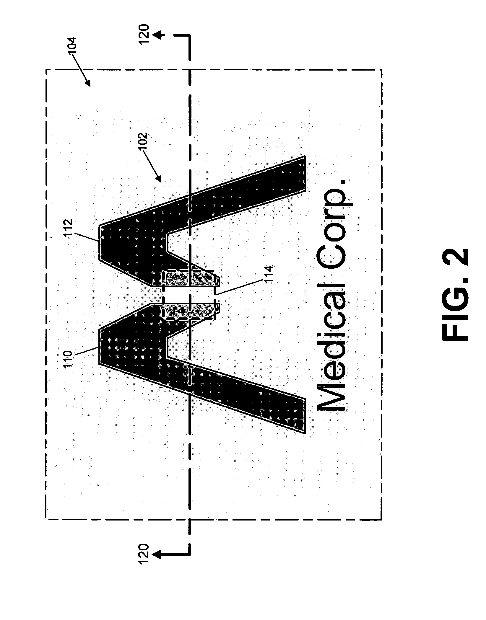
[0021]FIGS. 1-6 illustrate exemplary implementations of instruments having RFID tags formed in or on the material of the instrument handles having at least a portion of its surface comprised of, or covered by, a non-metallic material such as a hard plastic or polymeric material, or alternatively, an elastic,...


PUM


Abstract

Disclosed are exemplary implementations of an instrument having an RFID tag formed in or on the material of its handle. One or more antenna segments of the RFID tag may be formed from conductive material printed on or otherwise applied to a surface of the material or they may be formed from a conductive foil or other preformed material applied to the surface of the elastic material of the instrument handle. The antenna segments may be configured to represent at least a portion of a graphic, such as a company logo, for viewing by a user or handler of the instrument. At least a portion of the RFID tag and surrounding of the instrument handle may be covered by a protective material to prevent damage to the RFID tag as a result of repeated handling or subjection of the instrument to autoclaving, sterilization or caustic materials.

Description

FIELD OF THE INVENTION [0001] The present invention relates generally to radio frequency identification (RFID) tags and more particularly to the use of RFID tags on instrument handles. BACKGROUND OF THE INVENTION [0002] Radio frequency identification (RFID) tags frequently are used to track items as they are manufactured, shipped, or otherwise handled. In general, conventional RFID tags are created by forming a radio frequency (RF) antenna on a firm, solid substrate, such as hard plastic, paper or cardboard. An RFID chip having circuitry to enable the RFID functions is positioned on or near the RF antenna and the contacts of the RFID chip are electrically connected to the RF antenna. The RFID tag then may be attached to the tracked product or attached to a package, bill or envelope associated with the tracked product. [0003] While conventional RFID techniques are appropriate in many circumstances, these techniques have a number of shortcomings when used to implement RFID tags on ins...

Claims


Application Information

Patent Timeline
IPC IPC(8): G06Q30/00
CPCA61B19/44G06K19/07749A61B2019/448A61B90/90A61B90/98H01L2224/16225H01L2224/18
Inventor TETHRAKE, STEVEN M.NYCZ, JEFFREY H.PELO, MARK
Owner WARSAW ORTHOPEDIC INC
Why Eureka
Try Eureka