
Input device and mobile phone using the same

a technology of input device and mobile phone, which is applied in the direction of instruments, portable computer details, static indicating devices, etc., can solve the problems of increasing the number and complexity of key operations, complicated combined operations of operators, and the need for a large number of light-emitting devices, etc., and achieves the effect of easy input operation

Inactive Publication Date: 2006-03-02
PANASONIC CORP
View PDF11 Cites 18 Cited by
  • Summary
  • Abstract
  • Description
  • Claims
  • Application Information

AI Technical Summary

Benefits of technology

[0013] It is therefore the object of the present invention to provide an input device that offers an easy input operation and uniform lighting over the data entry section.
[0014] To achieve the object above, the input device of the present invention has a data entry section formed of a printed input portion having a “keyboard”; an electroluminescent (EL) device for illuminating the printed input portion; and a touch panel having a usable area at least, in size, equivalent to the printed input portion. By pressing a key of the printed input portion, the operator can carry out data entry with no complicated operations. At the same time, surface lighting of the EL device uniformly lights up the entire area of the input device.
[0015] The mobile phone of the present invention has a data entry section fixed to the housing of the phone and a controller connected to the data entry section. The data entry section further contains a printed input portion where the operator can input data through a “keyboard”; an electroluminescent (EL) device for illuminating the printed input portion; and a touch panel having a usable area equivalent to or greater, in size, than the printed input portion. The controller controls lighting of the EL device and detects a pushed position on the touch panel. Having a simple structure above, the mobile phone can offer an operator a variety of input operations and uniform lighting over the data entry section.

Problems solved by technology

However, to cope with complex input operations of a multi-functioned device with the use of the aforementioned conventional input device, it becomes necessary to increase the number of operation keys 3 and function keys 4 of input device 6; if not, requires to assign multi functions to a single key and therefore the operator has to go through complicatedly combined operations to select a desired function.
Such a structure increases parts number and complexity in key operations.
It has been another problem that a large number of light-emitting devices are required for uniformly lighting up input device 6.

Method used


Image

  • Input device and mobile phone using the same
  • Input device and mobile phone using the same
  • Input device and mobile phone using the same

Examples


embodiment

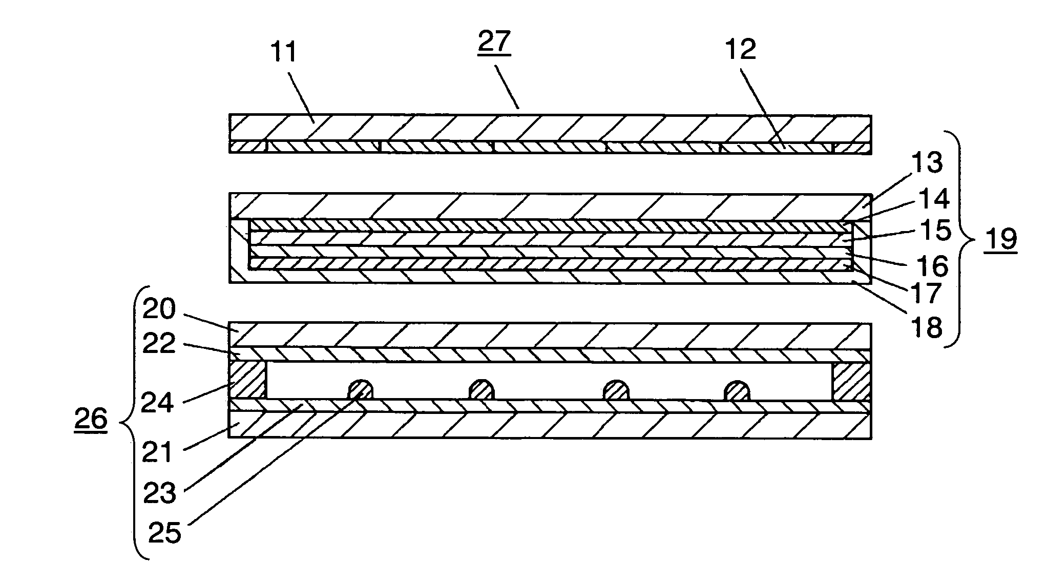
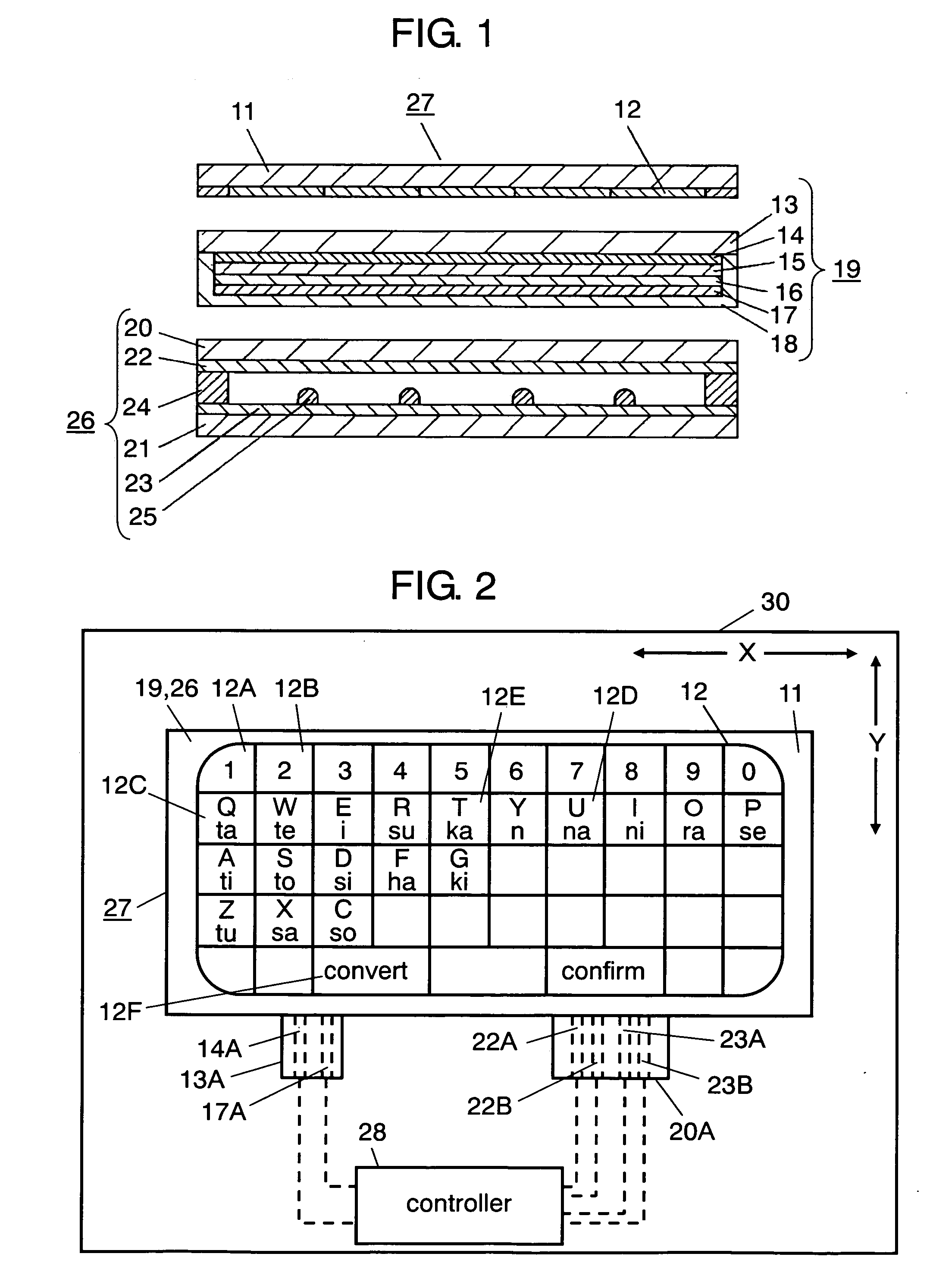
[0028]FIG. 1 is a sectional view of data entry section 27 of an input device of an embodiment of the present invention. FIG. 2 schematically shows the structure of input device 30 of the embodiment. As shown in those drawings, data entry section 27 of the embodiment contains light transmitting display sheet 11, EL device 19, and touch panel 26. It will be understood that FIG. 2 shows the keyboard of input device 30 with keys necessary for description of the embodiment.

[0029] As a novelty of the present invention, data entry section 27 has a keyboard layout. To provide the function, printed input portion 12, which bears numeric characters, kana (Japanese syllabic writing) in the JIS layout, and alphabets in the QWERTY layout, is disposed under display sheet 11. Printed input portion 12 contains a plurality of printed keys, such as 12A, 12B, and 12C. Display sheet 11 is a transparent film made of polyethylene terephthalate, polycarbonate, or the like. In this embodiment, kana (Japane...


PUM


Abstract

An input device having a data entry section and a controller. The data entry section has a layered structure of “keyboard”-equipped printed input portion, EL device, and touch panel. The controller controls the EL device and the touch panel. Since the printed input portion has keyboard layout, users can input data with ease. Furthermore, the surface lighting of EL device can provide the input device with uniform lighting, increasing visibility of the entire device.

Description

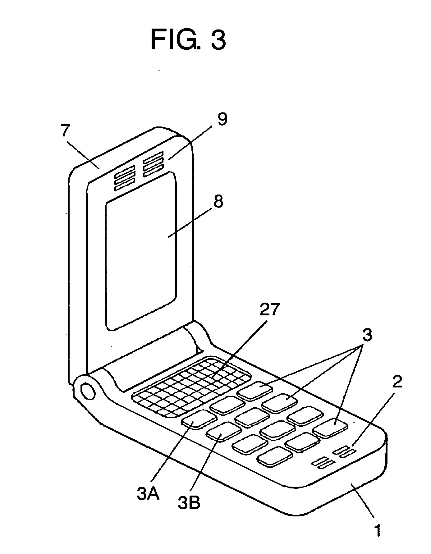
1. FIELD OF THE INVENTION [0001] The present invention relates to an input device used for various kinds of electronic equipment, such as a mobile phone and a personal computer, and also relates to a mobile phone using the input device. 2. BACKGROUND ART [0002] In recent years, advanced electronic equipment, such as a mobile phone and a personal computer equipped with high performance and multi functions, has been increasing. In such a trend, manufacturers have been seeking an input device capable of accepting various input style with simple operations, which is employed for the advanced equipments. [0003] Here will be described a mobile phone equipped with a conventional input device with reference to FIG. 4. [0004] The conventional mobile phone of FIG. 4 has fixed housing 1 and movable housing 7, both of which are made of insulating resin. Movable housing 7 is foldably attached to fixed housing 1. Fixed housing 1 contains, on the top surface, 3×4 vertically movable operation keys ...

Claims


Application Information

Patent Timeline
IPC IPC(8): G09G5/00
CPCG06F1/1616G06F1/1671G06F1/169G06F3/045G06F3/04886H01H2201/028H04M2250/22H01H2211/006H01H2219/018H01H2219/028H04M1/22H04M1/23H01H2209/052
Inventor NASU, TETSUTAROTANABE, KOJIKAWASUMI, AKITO
Owner PANASONIC CORP
Learn More