Position input device, remote control device, computer system and electronic equipment

a technology of remote control device and input device, which is applied in the field of position input device, remote control device, computer system and electronic equipment, to achieve the effect of convenient and fast operation, quick and easy utilization

Inactive Publication Date: 2007-08-02
WACOM CO LTD
View PDF14 Cites 19 Cited by
  • Summary
  • Abstract
  • Description
  • Claims
  • Application Information

AI Technical Summary

Benefits of technology

[0038]According to the certain aspects, positions can be input merely by sliding an operation element to an arbitrary / selected position, so that position input operations can be easily performed. As a result, operations can be performed quickly and easily utilizing, for example menu screens and GUIs (Graphic User Interfaces), so that equipment having complex functions can be operated by using simple procedures.
[0039]In certain aspects of this invention, in particular the sixth to ninth aspects, by opening and closing the lid it is possible to switch between operations using an operation element mounted on the lid, and operations using an external position indicator, so that the user can select the desired operation method to perform operations. Position input operations can easily be performed for various types of equipment, including equipment having complicated functions.

Problems solved by technology

Further, the operation element is supported in a manner enabling movement along the detection face, so that the user need merely move the operation element along the detection face, and need not maintain an appropriate distance between the operation element and the detection face.

Method used


Image

  • Position input device, remote control device, computer system and electronic equipment
  • Position input device, remote control device, computer system and electronic equipment
  • Position input device, remote control device, computer system and electronic equipment

Examples


first embodiment

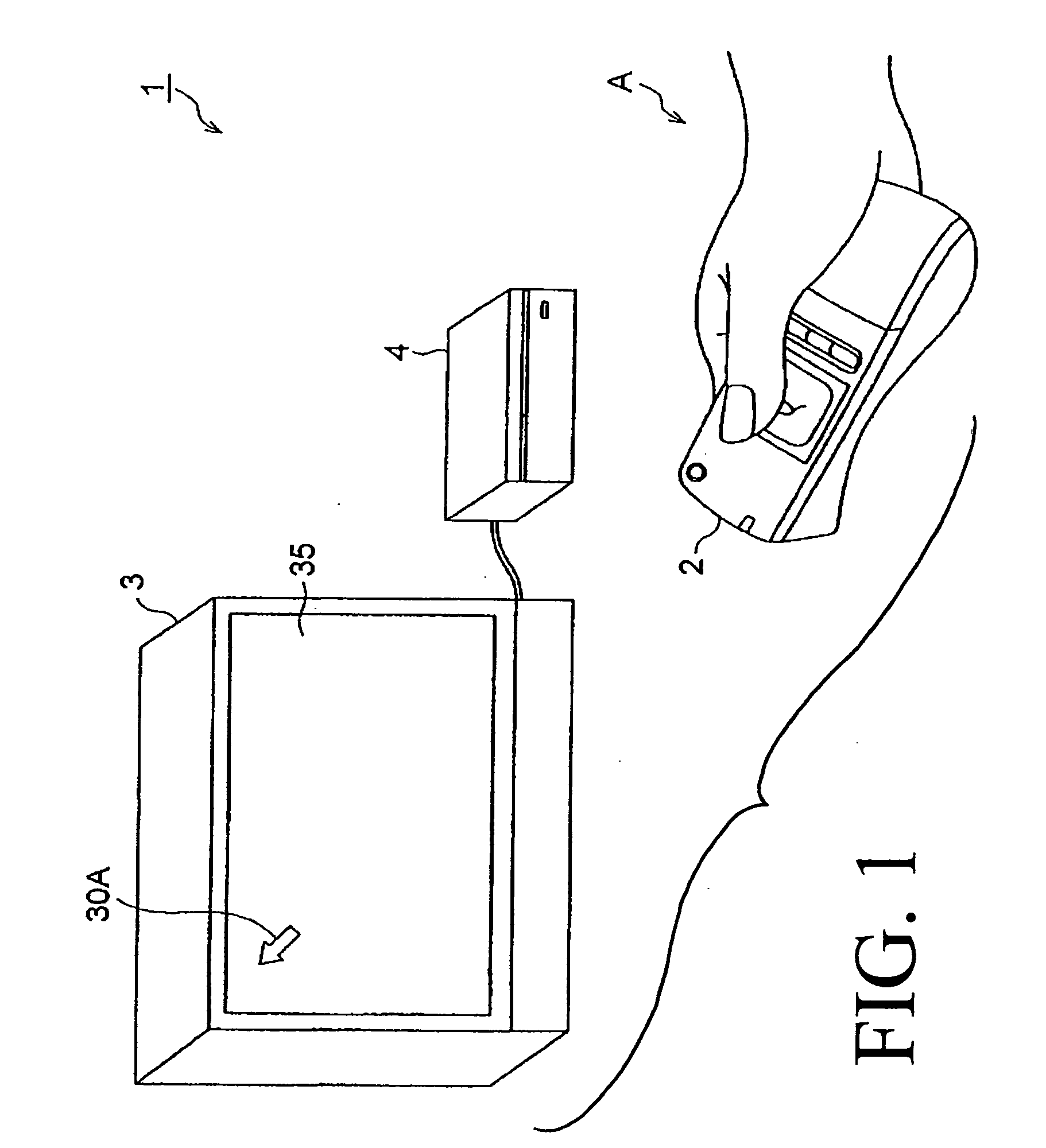
[0067]FIG. 1 shows an overview of the configuration of a computer system 1 of a first embodiment of the invention.

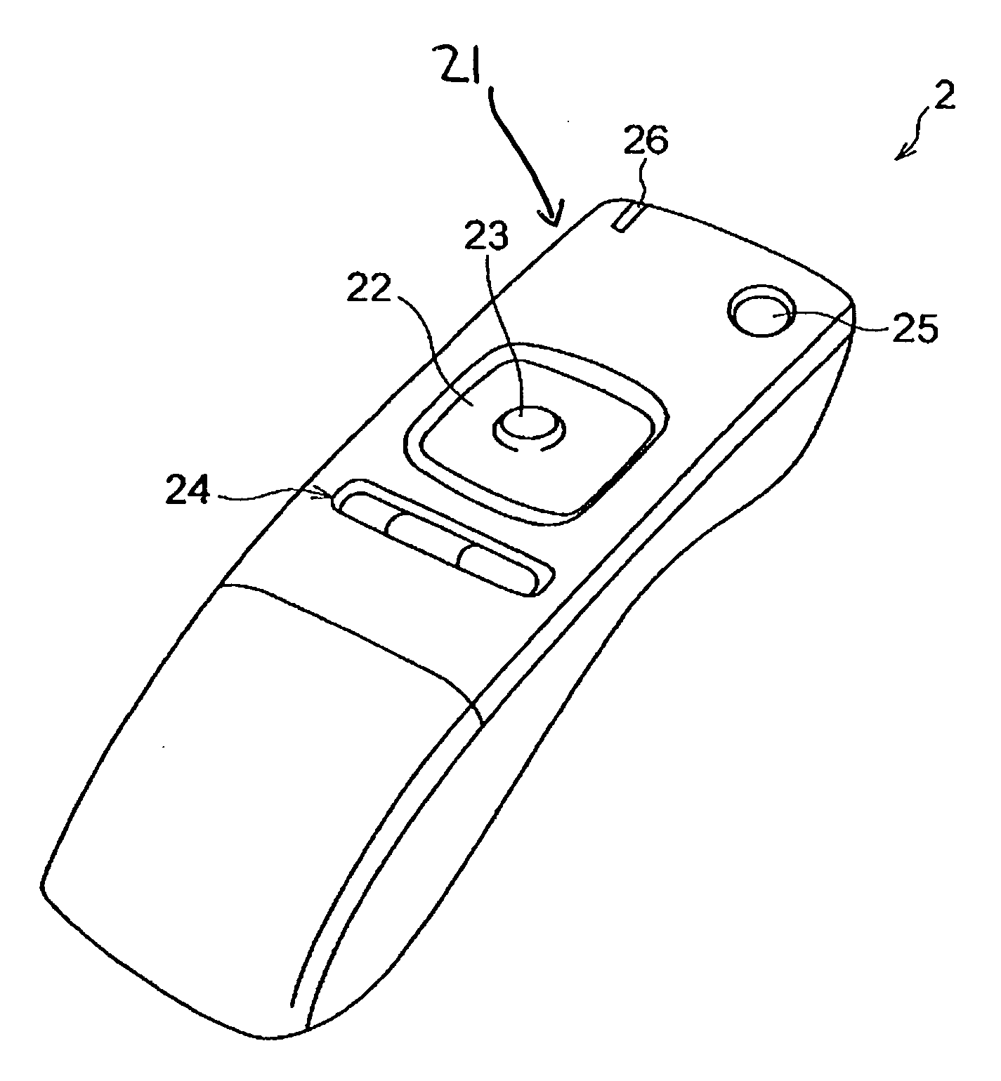
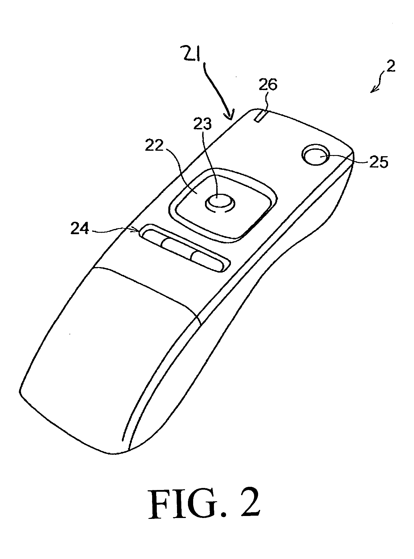
[0068]The computer system 1 in FIG. 1 comprises a remote control device 2, television receiver 3, and computer main unit 4. The remote control device 2 is a remote control device to perform instruction input operations for the computer main unit 4, and is held in the hand and operated by the user as indicated by the symbol A in FIG. 1, to wirelessly transmit signals indicating operation contents to the computer main unit 4.

[0069]As explained below, the computer main unit 4 is a computer which receives signals transmitted wirelessly from the remote control device 2 and executes various programs. The computer main unit 4 generates and outputs to the television receiver 3 display signals to display various screens related to programs being executed, and instructions received from the remote control device 2.

[0070]The television receiver 3 displays various screens on the dis...

second embodiment

[0125]FIG. 7 is a cross-sectional view of principal portions, showing the configuration of the position input operation portion 27 of a remote control device 2 of a second embodiment of the invention.

[0126]The remote control device 2 of this second embodiment is configured similarly to the remote control device 2 of the above first embodiment, except for the ball support portion 216, described below. Common constituent portions and parts are assigned the same symbols as used in connection with the first embodiment, and redundant drawings and explanations are omitted below.

[0127]The position input operation portion 27 shown in FIG. 7 is a position input device which is used in place of the position input operation portion 22 of the above first embodiment. This position input operation portion 27 is configured with a ball support portion 216 provided, in place of the friction material 214 in the position input operation portion 22, between the sensor base 213 and the flat pedestal 231...

third embodiment

[0130]FIG. 8 is a cross-sectional view of principal portions, showing the configuration of the position input operation portion 28 in a remote control device 2 of a third embodiment of the invention.

[0131]The remote control device 2 of this third embodiment is configured similarly to the remote control device 2 of the above first embodiment, except for the operation-side circuit 234, described below. Hence, common constituent portions and parts are assigned the same symbols as used above in connection with the first embodiment, and redundant drawings and explanations are omitted below.

[0132]The position input operation portion 28 shown in FIG. 8 is a position input device which is used in place of the position input operation portion 22 of the above first embodiment. This position input operation portion 28 is provided with a protuberance contact face 233A in place of the contact face 233. The user touches the protuberance contact face 233A with a finger.

[0133]The contact face 233A ...


PUM


Abstract

A position input device is provided which includes a sensor portion having a detection face, an operation element movable along the detection face of the sensor portion, and a position detection unit which detects the position of the operation element on the detection face. According to additional embodiments, the position input device includes a lid covering the detection face. The lid is movable between opened and closed states, and integrally supports the operation element so as to move integrally with the lid when the lid is opened and closed. A remote control device including the position input device and a wireless transmission unit are also provided. Also provided are computer systems and electronic devices.

Description

CROSS-REFERENCES TO RELATED APPLICATIONS[0001]The present application claims the benefit of priority from Japanese Application No. P2006-020435, filed on Jan. 30, 2006, the disclosure of which is incorporated herein by reference in its entirety.[0002]The present application also claims priority from Japanese Application No. P2006-020878, filed on Jan. 30, 2006, the disclosure of which is incorporated herein by reference in its entirety.FIELD OF THE INVENTION[0003]The present invention relates to a position input device to perform position input operations, a remote control device comprising this position input device, a computer system, and electronic equipment.BACKGROUND OF THE INVENTION[0004]Remote operation devices (so-called remote control devices) are used with numerous household electronic products, for example as disclosed in Japanese Patent Laid-open No. 05-056484. Many remote control devices comprise numerous keys corresponding to functions possessed by the equipment to be ...

Claims


Application Information

Patent Timeline
Patent Type & Authority Applications(United States)
IPC IPC(8): G09G5/00
CPCH04N5/4403H04N21/42222H04N2005/4432H04N2005/4428H04N21/42204H04N21/42206
Inventor ABE, MASAHIKO
Owner WACOM CO LTD
Why Eureka
Try Eureka