

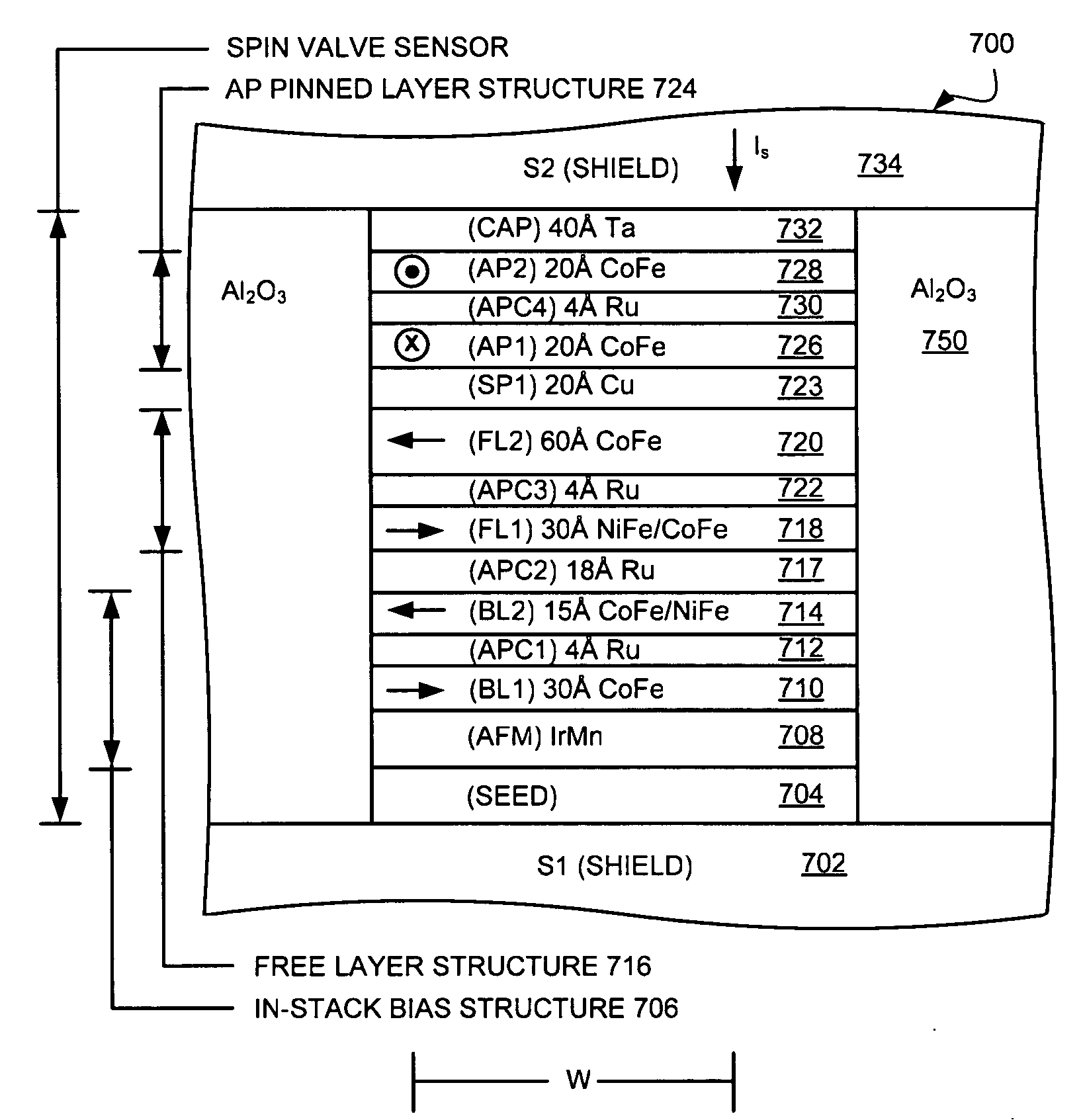
Sensor with in-stack bias structure providing enhanced magnetostatic stabilization
a technology of instack biasing and sensors, applied in the field of magnetic sensors, can solve problems such as poor pinned biasing layer b>120
- Summary
- Abstract
- Description
- Claims
- Application Information
AI Technical Summary
Benefits of technology
Problems solved by technology
Method used
Image

Examples
Embodiment Construction
[0033] The following description is the best embodiment presently contemplated for carrying out the present invention. This description is made for the purpose of illustrating the general principles of the present invention and is not meant to limit the inventive concepts claimed herein.
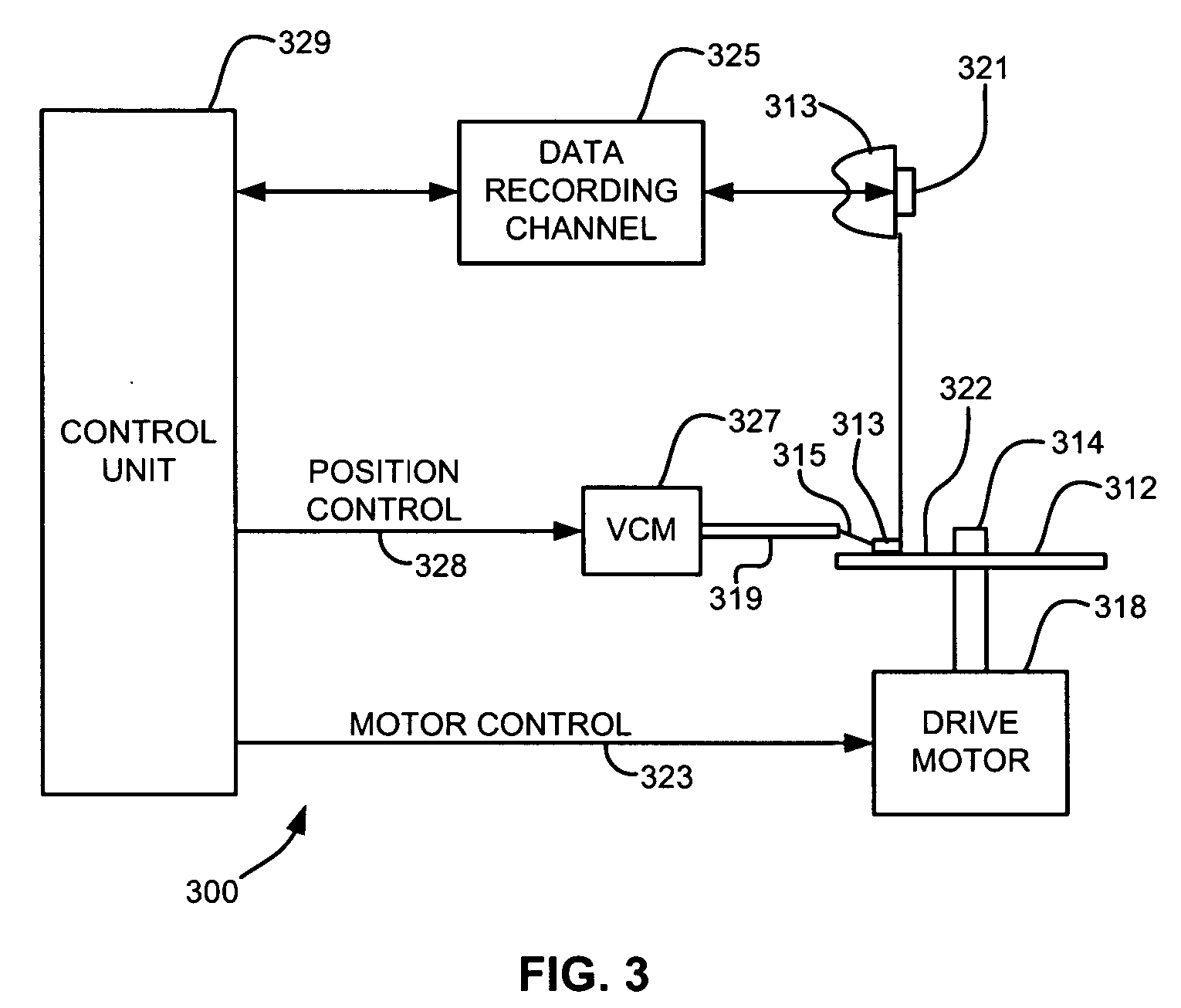
[0034] Referring now to FIG. 3, there is shown a disk drive 300 embodying the present invention. As shown in FIG. 3, at least one rotatable magnetic disk 312 is supported on a spindle 314 and rotated by a disk drive motor 318. The magnetic recording on each disk is in the form of an annular pattern of concentric data tracks (not shown) on the disk 312.
[0035] At least one slider 313 is positioned near the disk 312, each slider 313 supporting one or more magnetic read / write heads 321. As the disks rotate, slider 313 is moved radially in and out over disk surface 322 so that heads 321 may access different tracks of the disk where desired data are recorded. Each slider 313 is attached to an actuator ar...
PUM
| Property | Measurement | Unit |
|---|---|---|
| thickness | aaaaa | aaaaa |
| antiferromagnetic | aaaaa | aaaaa |
| magnetic moment | aaaaa | aaaaa |
Abstract
Description
Claims
Application Information