Method, system, and computer program product for remote storage and discovery of a path maximum transmission unit value on a network

a technology of remote storage and transmission unit value, applied in the field of data processing, can solve problems such as significant inefficiency, inefficiency created, and inefficiency involving both efficiency and security

Inactive Publication Date: 2006-03-02
IBM CORP
View PDF6 Cites 32 Cited by
  • Summary
  • Abstract
  • Description
  • Claims
  • Application Information

AI Technical Summary

Problems solved by technology

A recurring and frustrating problem is encountered when a packet, which was sent by a sending data processing system, is too large to be transmitted by a relaying data processing system, which receives it along the chosen path between the sending data processing system and the target data processing system.
Even if a packet starts out on a network segment with a large MTU, it may later arrive at a link with a smaller MTU, and the link with the smaller MTU may reject the packet as being too large for retransmission.
The fragments can be reassembled downstream to reconstruct the original large packet, but this packet fragmentation creates problems involving both efficiency and security.
Unfortunately, the simple solution described above creates significant inefficiency when multiple systems on a network send large packets and receive error messages.
The first inefficiency created by the solution described above relates to the increased time necessary to transmit the individual packet, which is rejected as being too large and subsequently retransmitted.
The second inefficiency relates to the increase in the number of packets transmitted.
The increase in the number of packets creates latency and delay with respect to all traffic on the network.
Both of these inefficiencies become yet more problematic as they are duplicated for several machines on a subnet.
These clients were not designed with the perception of ‘real time’ interaction with the network, and users will tolerate a substantial aggregate delay between the time at which information is sent and the time at which it is received.
Users are, however, generally less tolerant of the loss of information between the sending and receiving points, which sometimes occurs as a result of the need to resend packets, which is discussed above.

Method used


Image

  • Method, system, and computer program product for remote storage and discovery of a path maximum transmission unit value on a network
  • Method, system, and computer program product for remote storage and discovery of a path maximum transmission unit value on a network
  • Method, system, and computer program product for remote storage and discovery of a path maximum transmission unit value on a network

Examples


Embodiment Construction

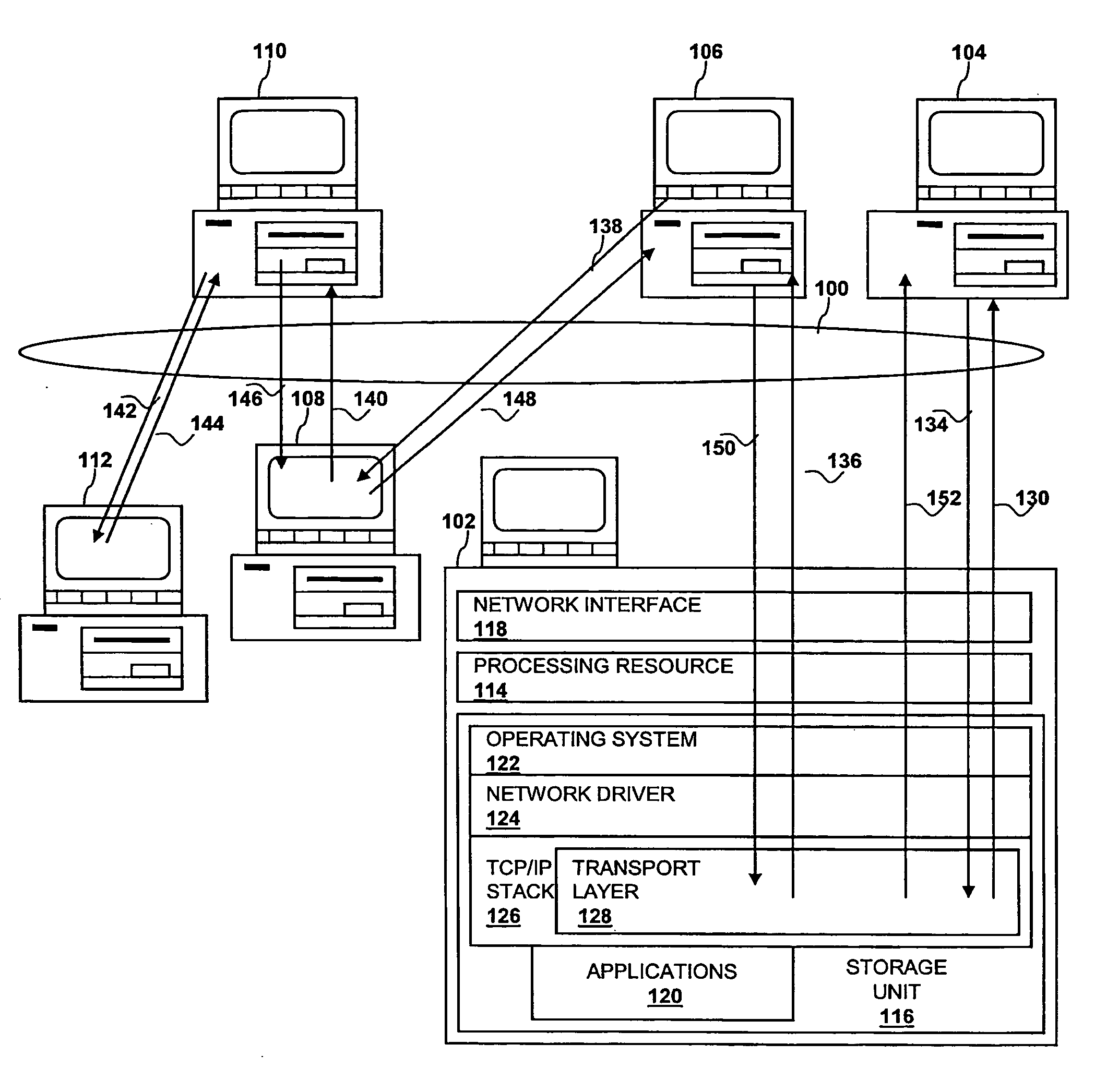
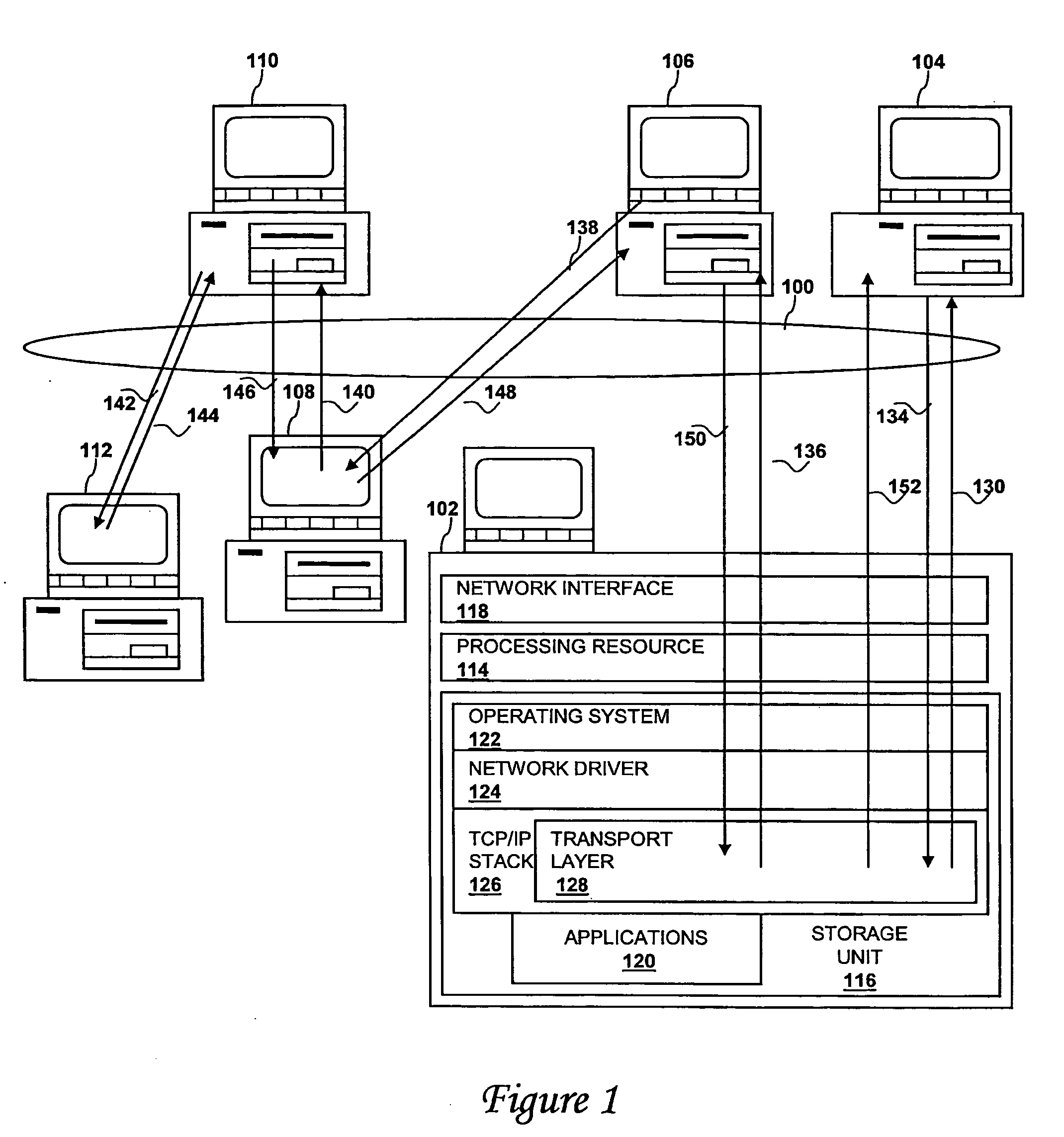
[0023] With reference now to the figures and in particular with reference to FIG. 1, there is depicted an exemplary network environment with which the present invention may be advantageously utilized. The illustrated network environment includes a local or wide area network 100, such as the Internet or another packetized digital network. A local data processing system 102 and a path maximum transmission unit value server 104 are attached to network 100. PMTU value server 104 can be implemented, for example, as a dedicated machine or a background process running on a data processing system that is primarily used for another application (e.g., operating in the background on a data processing system that primarily serves as an FTP server, an HTTP server, a simple mail transfer protocol (SMTP) and Post Office Protocol 3 (POP3) or Internet Message Access Protocol (IMAP) server, a client machine, or a file server). Additionally a first relay data processing system 106, a second relay data...


PUM


Abstract

A method, system, and computer program product for optimizing a message size for communication in a communication network are disclosed. The method comprises identifying a connection to a target, sending to a path maximum transmission unit value server (which is not the target) a request for a path maximum transmission unit value for the connection to the target, and, in response to receiving the path maximum transmission unit value for the connection to the target from the server, optimizing a communication by sending to the target a packet having a size in accordance with the value.

Description

BACKGROUND OF THE INVENTION [0001] 1. Technical Field [0002] The present invention relates in general to data processing and in particular to improving efficiency of data transmission and distribution within a data processing system network. Still more particularly, the present invention relates to a system, method and computer program product for storing on a server and delivering to a client a path maximum transmission unit value. [0003] 2. Description of the Related Art [0004] The profusion of applications exchanging data across networks now enables a range of technologies inconceivable only a few years ago. Applications exchanging data over a network range from email clients and servers to World Wide Web browsers communicating with servers to Voice-over-Internet-Protocol (VoIP) applications. [0005] Computers transmit data over the Internet in units called packets. Packets are transmitted across the Internet between a sending data processing system and a target data processing sy...

Claims


Application Information

Patent Timeline
Patent Type & Authority Applications(United States)
IPC IPC(8): H04J3/22
CPCH04L67/32H04L69/166H04L67/60
Inventor PANCHOLI, KETAN PRIYAKANTBANERJEE, DWIP N.QUIGG BROWN, DEANNA LYNNVENKATSUBRA, VENKAT
Owner IBM CORP
Why Eureka
Try Eureka