Wireless communication terminal apparatus, wireless communication base station apparatus, wireless communication system and telephone call connecting method
a technology of wireless communication base station and call connection method, which is applied in the direction of automatic exchange, electrical equipment, connection management, etc., can solve the problems of waste of radio resources and inability to perform setting, and achieve the effect of reducing the message size of call connection
- Summary
- Abstract
- Description
- Claims
- Application Information
AI Technical Summary
Benefits of technology
Problems solved by technology
Method used
Image
Examples
embodiment 1
[0048]First, general call connection steps for a radio communication terminal apparatus (hereinafter “UE (User Equipment)”) and a radio communication base station apparatus (hereinafter “Node B”) will be explained using FIG. 5. In ST101 in FIG. 5, the UE transmits an RRC connection request message to Node B, and, in ST102, Node B transmits an RRC connection setup message to the UE in response to the RRC connection request message and reports UE identity and channel setting for control information or the like.
[0049]In ST103, the UE performs a channel setting on the UE side according to the content reported with the RRC connection setup message and transmits an RRC connection setup complete message to Node B as a report on completion of setting.
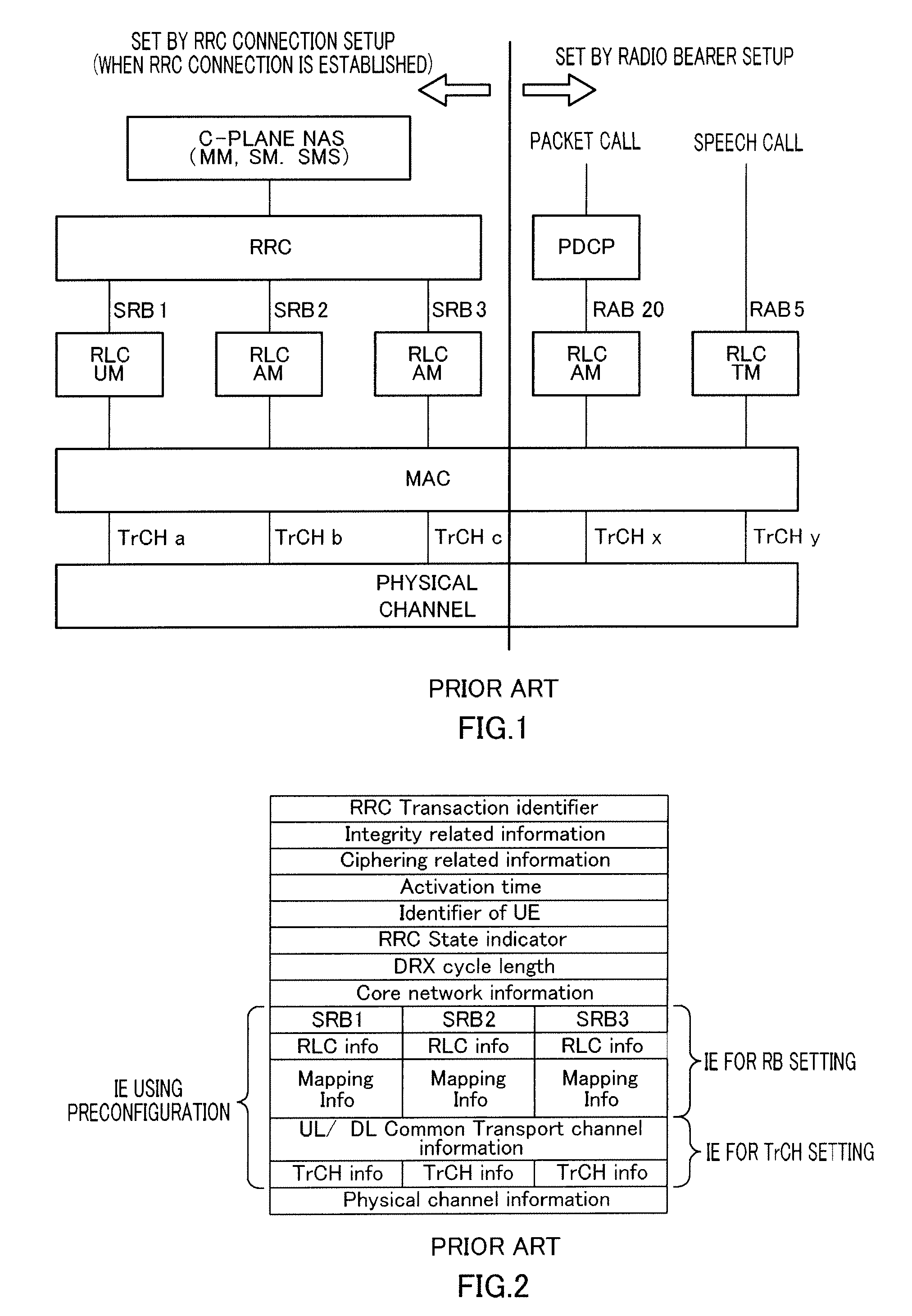
[0050]RRC connection establishment is completed through these processing in ST101 to ST103. In this RRC connection establishment, RB1 (applying an RLC UM mode), RB2 (applying RLC AM for transmission of an RRC message not including a NAS message...
embodiment 2
[0089]Although a case has been described with Embodiment 1 where the UE holds cell level information of one cell, Embodiment 2 of the present invention will describe a case where the UE holds cell level information of a plurality of cells as shown in FIG. 16.
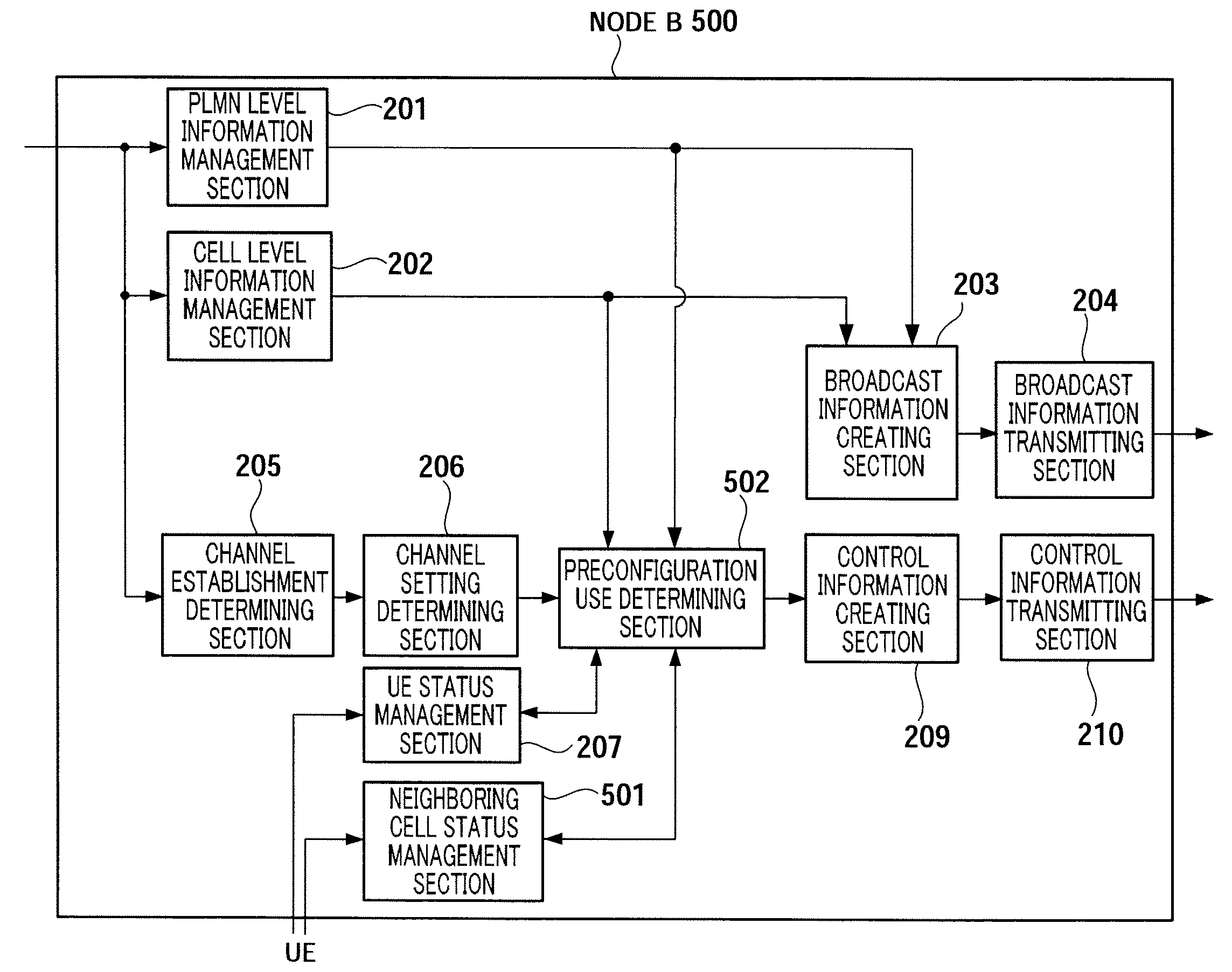
[0090]FIG. 17 is a block diagram showing the configuration of Node B 500 according to Embodiment 2 of the present invention. FIG. 17 differs from FIG. 6 in that neighboring cell status management section 501 is added and preconfiguration use determining section 208 is replaced by preconfiguration use determining section 502.
[0091]In FIG. 17, neighboring cell status management section 501 acquires a status showing whether or not a UE holds PLMN information and cell level information of a neighboring cell from the UE, manages the acquired UE status and ID of the UE, and, upon receiving a request for a status report of the UE from preconfiguration use determining section 502, sends back the corresponding status to preconfiguration ...
embodiment 3
[0104]FIG. 21 is a block diagram showing the configuration of Node B 800 according to Embodiment 3 of the present invention. FIG. 21 differs from FIG. 6 in that neighboring cell information management section 801 is added, broadcast information creating section 203 is replaced by broadcast information creating section 802 and preconfiguration use determining section 208 is replaced by preconfiguration use determining section 803.
[0105]In FIG. 21, neighboring cell information management section 801 manages information needed to identify a cell such as a frequency band and scrambling code (hereinafter “neighboring cell information”) and outputs the managed neighboring cell information to broadcast information creating section 802 and preconfiguration use determining section 803.
[0106]Broadcast information creating section 802 creates broadcast information including the PLMN level information outputted from PLMN level information management section 201, the cell level information outpu...
PUM
 Abstract
Description
Claims
Application Information
 - R&D
- Intellectual Property
- Life Sciences
- Materials
- Tech Scout
- Unparalleled Data Quality
- Higher Quality Content
- 60% Fewer Hallucinations
Browse by: Latest US Patents, China's latest patents, Technical Efficacy Thesaurus, Application Domain, Technology Topic, Popular Technical Reports.
© 2025 PatSnap. All rights reserved.Legal|Privacy policy|Modern Slavery Act Transparency Statement|Sitemap|About US| Contact US: help@patsnap.com


