[0014] As described above, by providing the fuse-connecting units of the first group and the fuse-connecting units of the second group on the case of one electric junction box, no matter the electric junction box is installed in a right hand drive vehicle or a left hand drive vehicle, it is possible to place fuses mounted in the fuse-connecting units in a location facing the fuse-replacement opening provided on the vehicle-body side and to replace melted-down fuses through the fuse-replacement opening. Consequently, the electric junction box can be used in both a right hand drive vehicle and a left hand drive vehicle, and there is no need to provide separately an electric junction box specific for a right hand drive vehicle and an electric junction box specific for a left hand drive vehicle, thereby making it possible to reduce the number of parts.
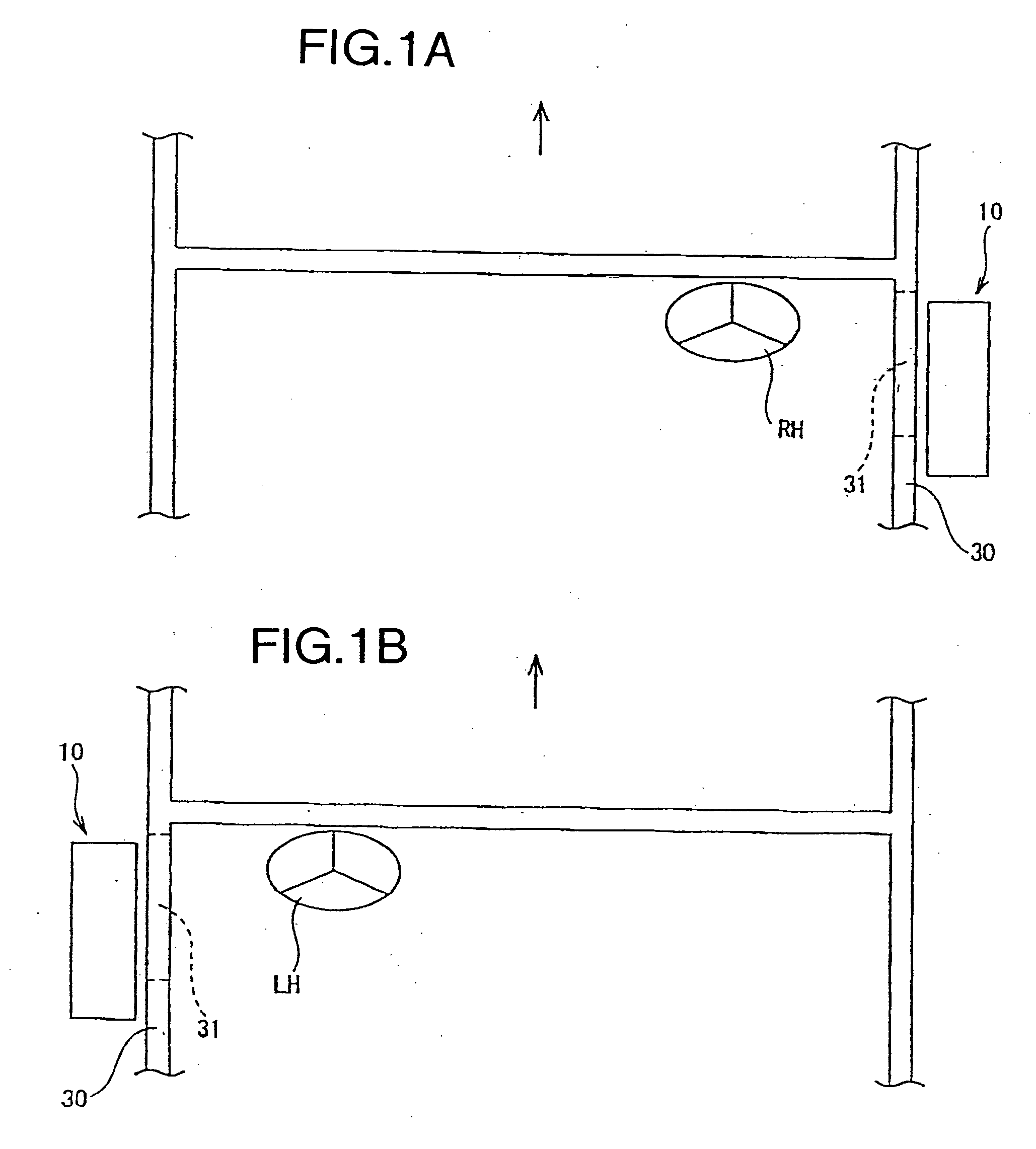
[0016] The electric junction box is placed slightly to the right-side of the fuse-replacement opening when installed in a right hand drive vehicle, and slightly to the left-side of the fuse-replacement opening when installed in a left hand drive vehicle. Consequently, the shared fuse-connecting units are provide in the middle region along the left-right direction; the fuse-connecting units for a right hand drive vehicle are placed to the left of the shared fuse-connecting units; and the fuse-connecting units for a left hand drive vehicle are placed to the right of shared fuse-connecting units. In other words, the fuse-connecting units for a right hand drive vehicle and the fuse-connecting units for a left hand drive vehicle are located left-right symmetrically with respect to the shared fuse-connecting units located in the middle region, and the required fuse-connecting units are placed in the location facing the fuse-replacement opening. Further, the number (A) of the shared fuse-connecting units and the number (B) of fuse-connecting units for either a right hand drive vehicle or a left hand drive vehicle are such that the ratio A:B is in the range 5:5-7:3 so that more than half of the fuses are fitted in the shared fuse-connecting units. Consequently, there are not too many fuses fitted in the fuse-connecting units for either a right hand drive vehicle or a left hand drive vehicle, and there are also not too many fuse-connecting units that are not used to connect with fuse terminals. Therefore, there is no significant waste occurring in the internal circuit, and there is also no significant increase in the size of the electric junction box.
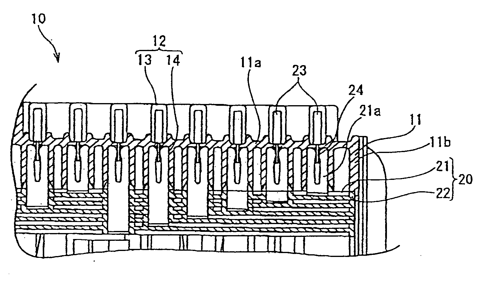
[0019] According to the configuration described above, for the fuse-connecting units for a left hand drive vehicle that are not used in an electric junction box for installation in a right hand drive vehicle, or for the fuse-connecting units for a right hand drive vehicle that are not used in an electric junction box for installation in a left hand drive vehicle, no fuse-mounting portions are provided and the corresponding area on the case forms a closed surface area. Therefore, it is possible to prevent accidentally fitting a fuse in a fuse-connecting unit that is not used. Although differently shaped cases are provided for a right hand drive vehicle and a left hand drive vehicle, the only difference is the existence or nonexistence of some of the fuse-mounting portions on the external surfaces of the cases. Therefore, by placing a
bushing in a case-forming die, the same die can be used to form both the case for a right hand drive vehicle and the case for a left hand drive vehicle, thereby reducing die costs. Further, on the inner surface of the case for a right hand drive vehicle and on the inner surface of the case for a left hand drive vehicle, fuse-connecting terminal receptacles for all fuse-connecting units are provided, and all fuse-connecting terminals of the internal circuit are fitted in the fuse-connecting terminal receptacles. Therefore, there is no need to change the internal circuit for a right hand drive vehicle and a left hand drive vehicle. Except the case, on which the fuse-mounting portions are provided, the electric junction box can be used in both a right hand drive vehicle and a left hand drive vehicle.
[0021] According to the configuration described above, by fitting the fuse connectors into fuse-mounting portions linked to the fuse-connecting terminal receptacles containing fuse-connecting terminals that are not in use, fuse-connecting terminals are connected to electric wires of an
external circuit; and similarly, by fitting the joint-connectors, the fuse-connecting terminals can be connected to each other to form a different circuit; thereby making it possible to make effective use of the fuse-connecting terminals that are not used to connect fuses.
[0022] As described above, according to the present invention, by providing the shared fuse-connecting units, the fuse-connecting units for a right hand drive vehicle and the fuse-connecting units for a left hand drive vehicle on the case of the electric junction box, no matter the electric junction box is for installation in a right hand drive vehicle or a left hand drive vehicle, it is possible to place fuses mounted in the required fuse-connecting units in a location facing the same fuse-replacement opening formed on the vehicle-body side and to replace melted-down fuses through the fuse-replacement opening. Consequently, the electric junction box can be used in both a right hand drive vehicle and a left hand drive vehicle, and there is no need to provide separately an electric junction box specific for a right hand drive vehicle and an electric junction box specific for a left hand drive vehicle, thereby making it possible to reduce the number of parts.
[0024] Further, by fitting fuse connectors into the fuse-connecting units for a left hand drive vehicle in the electric junction box for installation in a right hand drive vehicle or into fuse-connecting units for a right hand drive vehicle in the electric junction box for installation in a left hand drive vehicle, the fuse-connecting terminals are connected to electric wires of an
external circuit. Similarly, by fitting joint-connectors, the fuse-connecting terminals are connected to each other to form a different circuit. Therefore, fuse-connecting terminals that are not used to connect fuse terminals can be used effectively.

