Eureka AIR delivers breakthrough ideas for toughest innovation challenges, trusted by R&D personnel around the world.

Mobile satellite communication system

a satellite communication and mobile technology, applied in the field of moving body satellite communication apparatus, can solve problems such as character deterioration, and achieve the effect of accepting character deterioration

Inactive Publication Date: 2006-03-02
MITSUBISHI ELECTRIC CORP
View PDF4 Cites 16 Cited by
  • Summary
  • Abstract
  • Description
  • Claims
  • Application Information

AI Technical Summary

Benefits of technology

[0008] The present invention has been made in view of this point, and in a moving body satellite communication apparatus including an antenna mounted on a moving body and having an anisotropic radome, 90° phase combiners connected to the antenna and constituting control systems of at least two channels for each of transmission and reception, a variable phase shifter inserted in each of the control systems of the two channels, a first variable attenuator connected in series to the variable phase shifter, and an antenna control circuit for performing attitude control of the antenna according to a relative positional relation between the moving body and a satellite, the antenna control circuit includes a first correction table storing radome correction data for frequencies and polarization angles of the antenna, and the variable phase shifter and the first variable attenuator are contr

Problems solved by technology

However, in an antenna with a radome mounted on a moving body such as an aircraft, since the height of the radome is restricted, the hemispherical curved surface of the constant incident angle as stated above can not be adopted, and accordingly, the loss due to the transmission of an electric wave through the radome, and the characteristic deterioration must be accepted.

Method used


Image

  • Mobile satellite communication system
  • Mobile satellite communication system
  • Mobile satellite communication system

Examples


Embodiment Construction

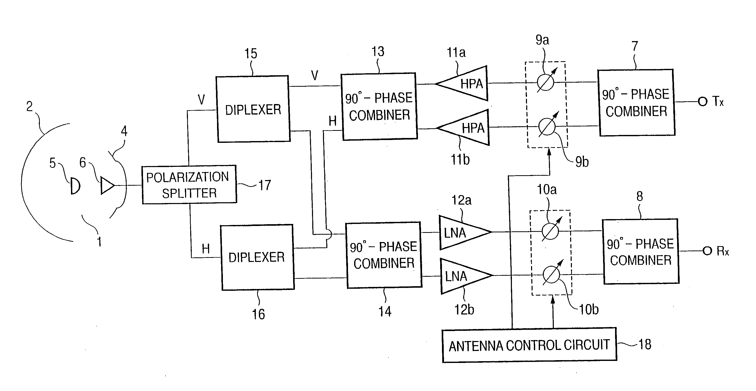
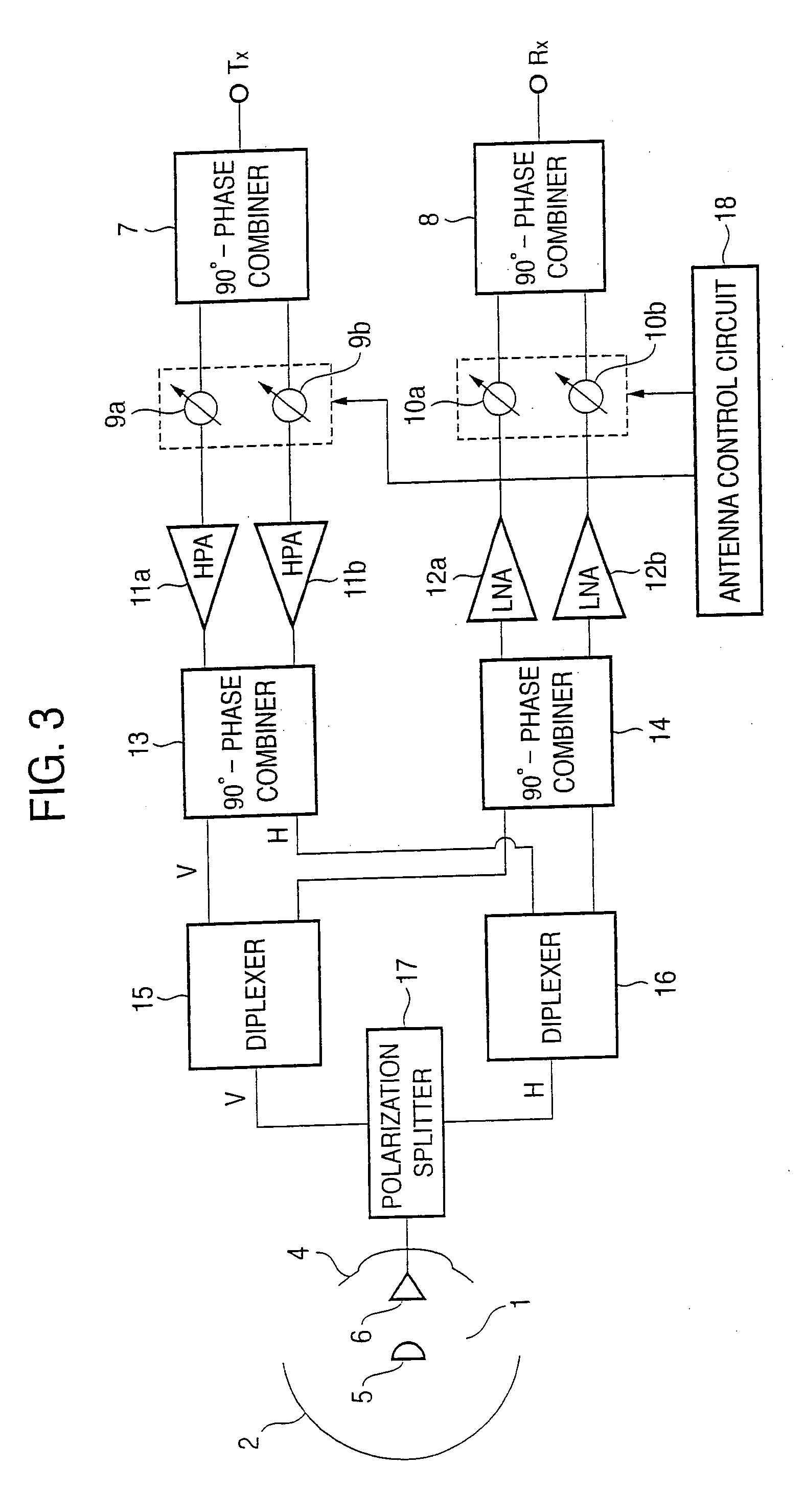
[0016]FIG. 4 is a structural view of an antenna system according to an embodiment of the invention. Structural portions similar to the conventional apparatus described in FIG. 3 are denoted by the same characters, and here, with emphasis on newly added novel portions in relation to radome correction, their structure will be described. In the drawing, reference numerals 19a and 19b denote variable attenuators inserted in series to transmission side variable phase shifters 9a and 9b; 20a and 20b, variable attenuators inserted in series to reception side variable phase shifters 10a and 10b; 21, a variable attenuator inserted to an input side of a 90° phase combiner 7; and 22, a storage medium of data relating to radome correction. When, for example, a transmitter signal to a satellite is inputted to a Tx terminal, it enters the 90° phase combiner 7 through the variable attenuator 21, and is divided into two channels there. The variable phase shifters 9a and 9b and the variable attenuat...


PUM


Abstract

In a moving body satellite communication apparatus for performing communication with a satellite by an antenna with a radome mounted on a moving body such as an aircraft, loss due to transmission through the radome, and distortion of polarization characteristics are compensated in the inside of the antenna. Variable phase shifters 9a and 9b and variable attenuators 19a and 19b, and variable phase shifters 10a and 10b and variable attenuators 20a and 20b are respectively controlled as one body in each channel, and the whole power EIRP radiated from the antenna is also optimally controlled by a common variable attenuator 21 inserted independently from the variable attenuators 19a and 19b, and therefore, radome correction and EIRP control can be simultaneously realized by a relatively simple circuit.

Description

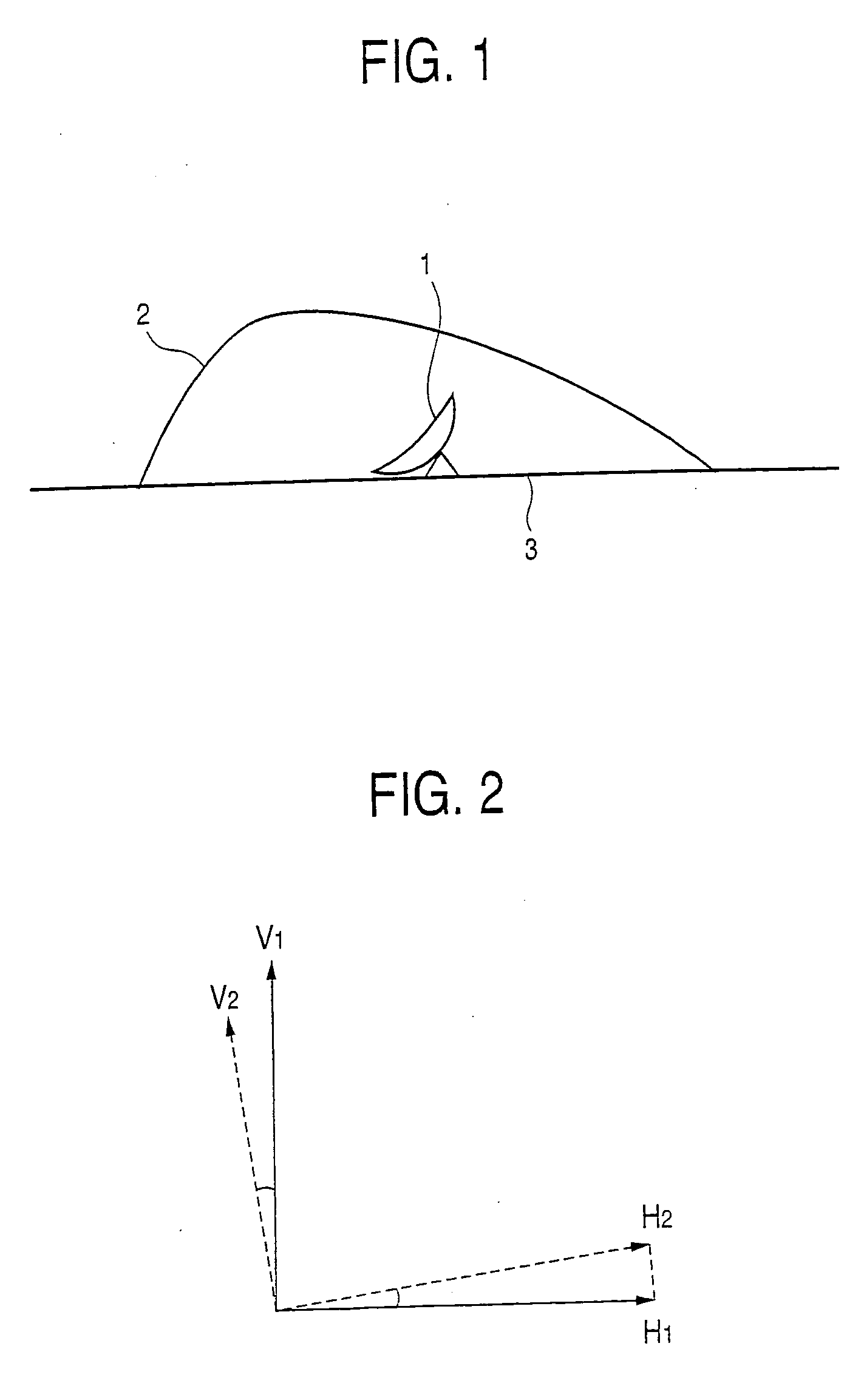
TECHNICAL FIELD [0001] The present invention relates to a moving body satellite communication apparatus, and particularly to a moving body satellite communication apparatus in which in an antenna with a radome mounted on a moving body such as an aircraft, loss due to transmission through the radome, and distortion of polarization characteristics are compensated in the inside of the antenna. BACKGROUND ART [0002] In general, in a case where a radome is placed over an antenna, in order to resolve the deterioration of antenna radiation characteristics due to the radome, a hemispherical radome curved surface is adopted so that even if the antenna is rotated, the incident angle of an electric wave becomes constant. [0003] However, in an antenna with a radome mounted on a moving body such as an aircraft, since the height of the radome is restricted, the hemispherical curved surface of the constant incident angle as stated above can not be adopted, and accordingly, the loss due to the tran...

Claims


Application Information

Patent Timeline
IPC IPC(8): H04B7/19H01Q1/28H01Q1/42H04B7/185
CPCH01Q1/28H01Q1/421H04B7/18532H04B7/18508H04B7/1853H04B7/18506
Inventor TAKEUCHI, NORIONAITOU, IZURUSAKAI, EIICHISHIMAWAKI, YUTAKA
Owner MITSUBISHI ELECTRIC CORP
Why Eureka
Eureka Blog
Learn More