
Wafer-to-wafer control using virtual modules

Inactive Publication Date: 2006-03-02
IBM CORP +1
View PDF9 Cites 41 Cited by
  • Summary
  • Abstract
  • Description
  • Claims
  • Application Information

AI Technical Summary

Problems solved by technology

Processing tools used in the semiconductor industry have developed into complex processing systems having a number of associated process modules.
This can create new opportunities for tailored control and optimization of segments of the process sequence on a lot-to-lot basis or even on a wafer-to-wafer basis, but new challenges can also be created.
If the factory control system cedes control over the wafers to the tool platform, then it also must cede direct knowledge of what actually happens to the wafers to the same platform.
One limitation of this arrangement is that recipes cannot be associated with the physical module, because the physical module is used more than once.

Method used


Image

  • Wafer-to-wafer control using virtual modules
  • Wafer-to-wafer control using virtual modules
  • Wafer-to-wafer control using virtual modules

Examples


Embodiment Construction

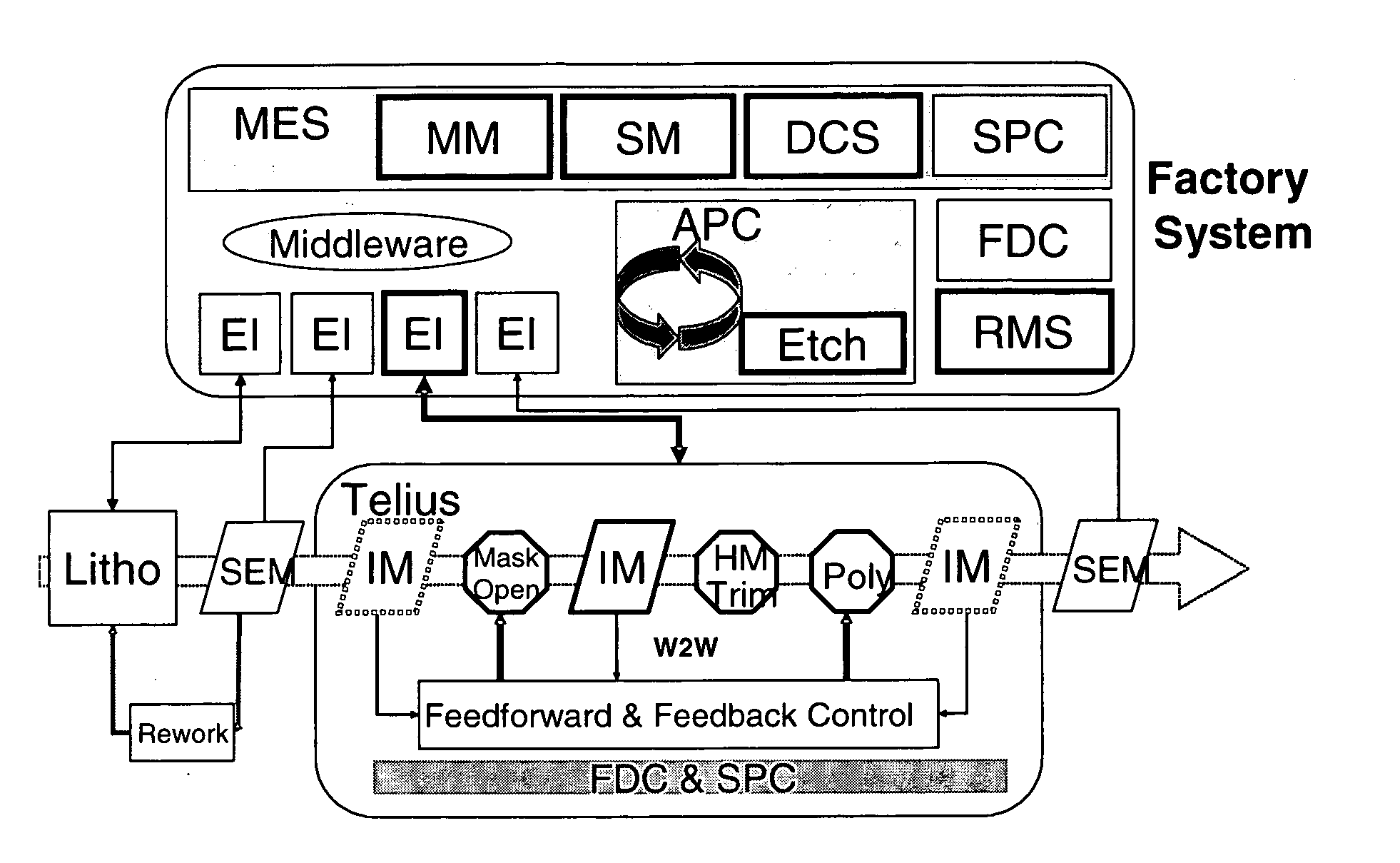
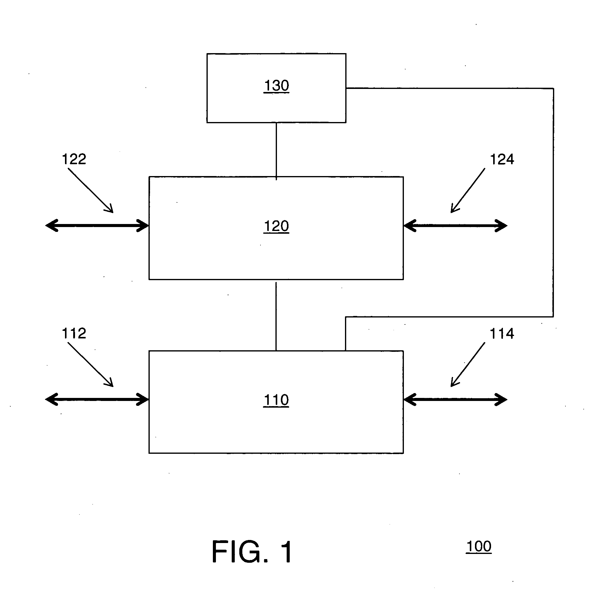
[0027]FIG. 1 shows an exemplary block diagram of a processing system in accordance with an embodiment of the present invention. In the illustrated embodiment, a processing system 100 comprises a processing tool 110, a controller 120 coupled to the processing tool 110, and a manufacturing equipment system (MES) 130 that is coupled to the controller 120 and to the processing tool 110. In addition, at least one of the processing tool 110, the controller 120, and the MES 130 can comprise a Graphical User Interface (GUI) component and / or a database component (not shown). In alternate embodiments, the GUI component and / or the database component are not required.

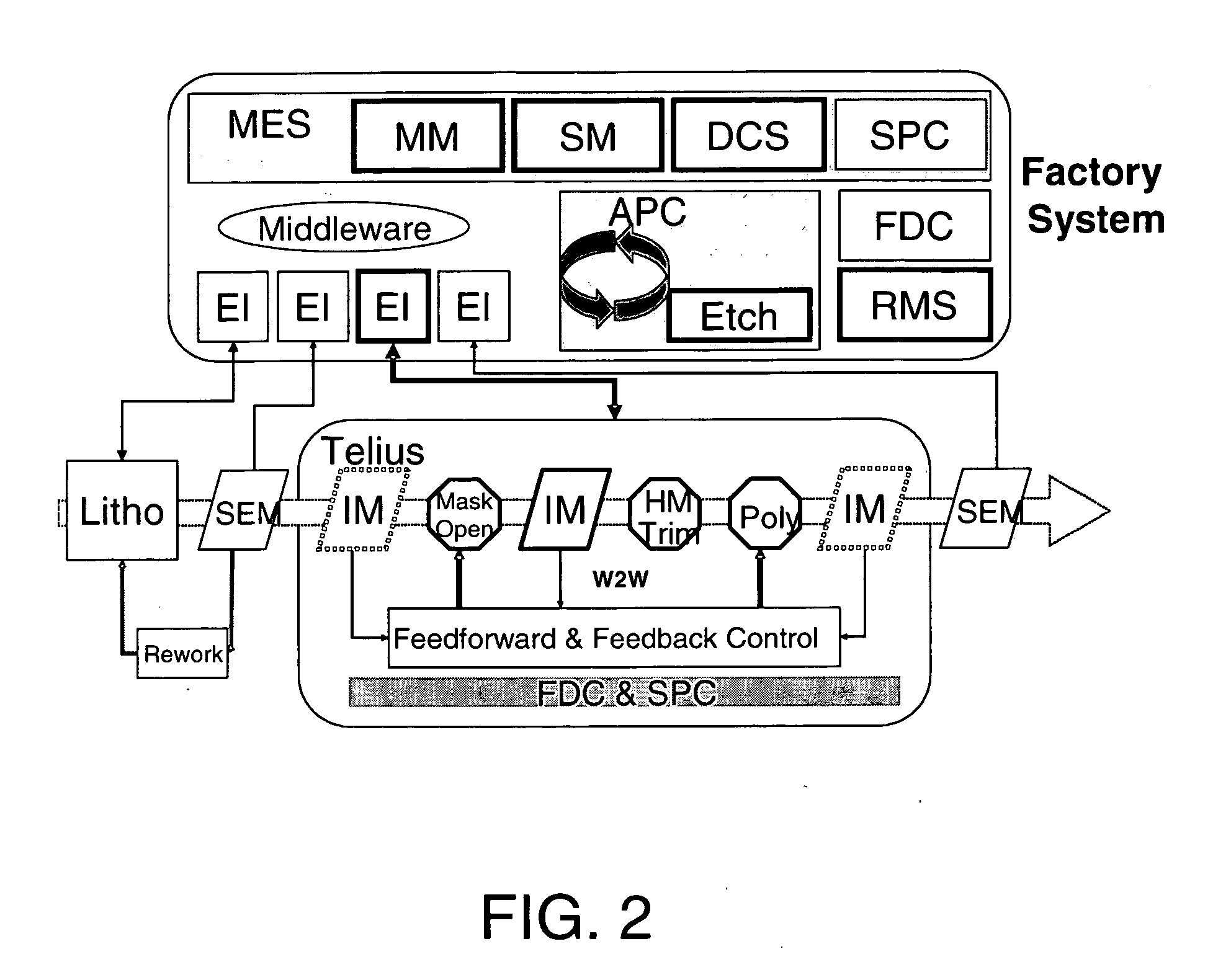
[0028] Some setup and / or configuration information can be obtained by the processing tool 110 and / or the controller 120 from the factory system 130. Factory level business rules can be used to establish a control hierarchy. For example, the processing tool 110 and / or the controller 120 can operate independently, or can be controll...


PUM


Abstract

The invention relates to controlling a semiconductor processing system. Among other things, the invention relates to a run-to-run controller to create virtual modules to control a multi-pass process performed by a multi-chamber tool during the processing of a semiconductor wafer.

Description

CROSS-REFERENCE TO RELATED APPLICATIONS [0001] This application is related to U.S. Non-Provisional patent application Ser. No. 10 / ______, entitled “Process Control Using Physical Modules and Virtual Modules,” attorney docket 071469-0310051, filed on even date herewith, the contents of which are incorporated herein by reference in its entirety.FIELD OF THE INVENTION [0002] The invention relates to developing process models for semiconductor wafer processing. More particularly, the invention relates to a run-to-run controller to create virtual modules to control a multi-pass process performed by a multi-chamber tool during the processing of a semiconductor wafer. BACKGROUND OF THE INVENTION [0003] Processing tools used in the semiconductor industry have developed into complex processing systems having a number of associated process modules. Due at least in part to this development trend, the dividing line between the tool control systems and the factory control systems are becoming in...

Claims


Application Information

Patent Timeline
IPC IPC(8): G06F19/00
CPCG05B19/41865H01L22/20G05B2219/45031Y02P80/114Y02P90/20Y02P90/86
Inventor FUNK, MERRITTNATZLE, WESLEY
Owner IBM CORP
Learn More