Street sweeper with vacuumized dust control

a technology of dust control and street sweeper, which is applied in the direction of suction cleaners, construction, way cleaning, etc., can solve the problems of limited arrangement of rotary brooms between front wheel and rear wheel assembly, inconvenient use of water, and inability to easily find water

Inactive Publication Date: 2006-03-09
ENGEL GREGORY J +1
View PDF24 Cites 25 Cited by
  • Summary
  • Abstract
  • Description
  • Claims
  • Application Information

AI Technical Summary

Benefits of technology

[0019] Having thus described embodiments of the present invention and enumerated several significant aspects and features thereof, it is the principal object of the present invention to provide a street sweeper which features, in part, vacuumized dust control.

Problems solved by technology

Prior art street sweeper devices are often built on and about custom chassis not generally suited for economy of speed or having attributes geared toward desirable roadability qualities.
Some arrangements, such as rotary broom placement between the front wheel and rear wheel assemblies, are often limited, necessitating the use of smaller rotary brooms the dimensions of which are restricted by the available distance between the roadway and the chassis of the conventional truck.
The use of water is not always economical, water may not be readily available for dust control, large water flow may be required for effective dust control, thereby necessitating frequent refilling stops due to limited tank capacity, and the use of water at higher speeds may not be effective.

Method used


Image

  • Street sweeper with vacuumized dust control
  • Street sweeper with vacuumized dust control
  • Street sweeper with vacuumized dust control

Examples


Embodiment Construction

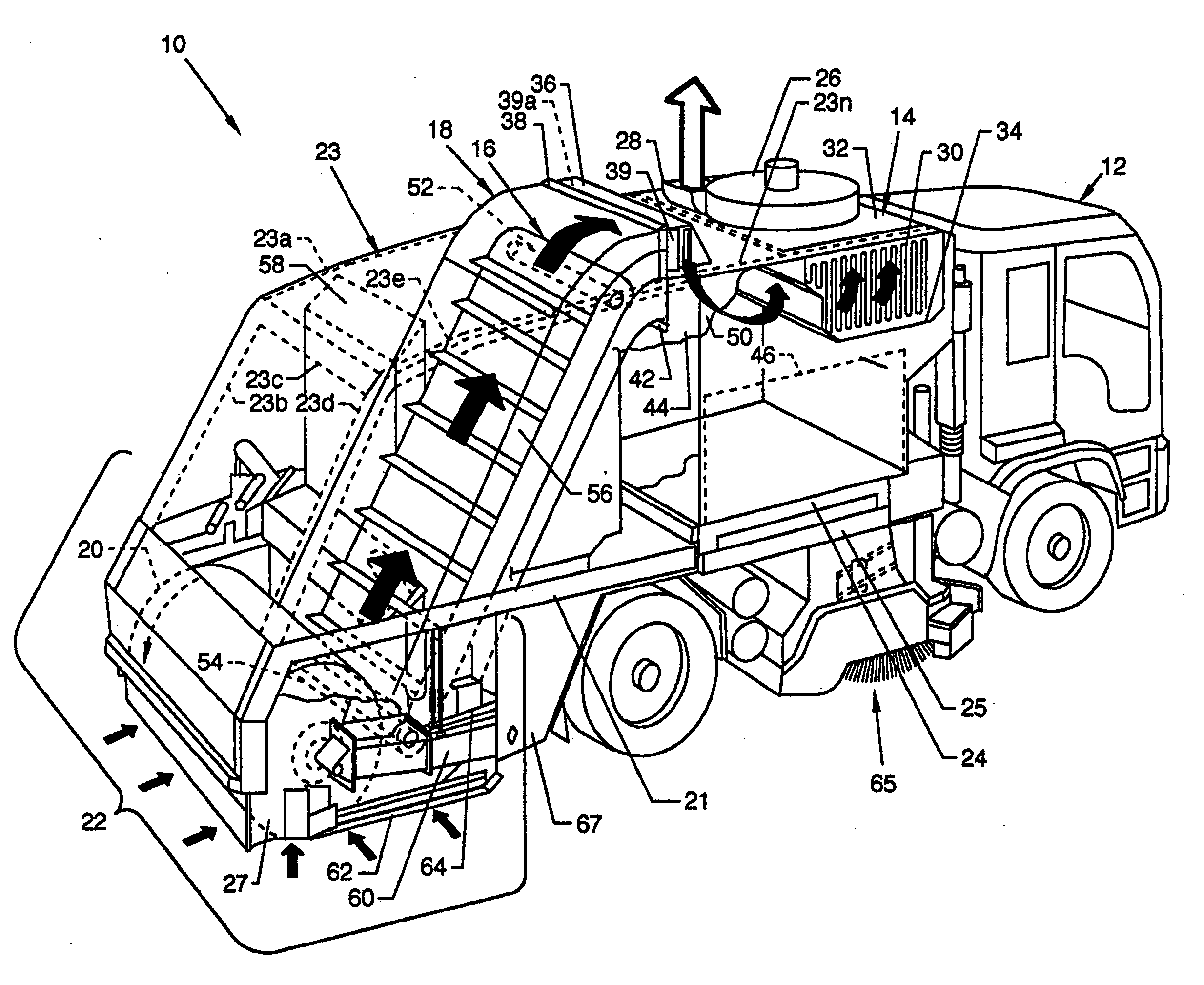
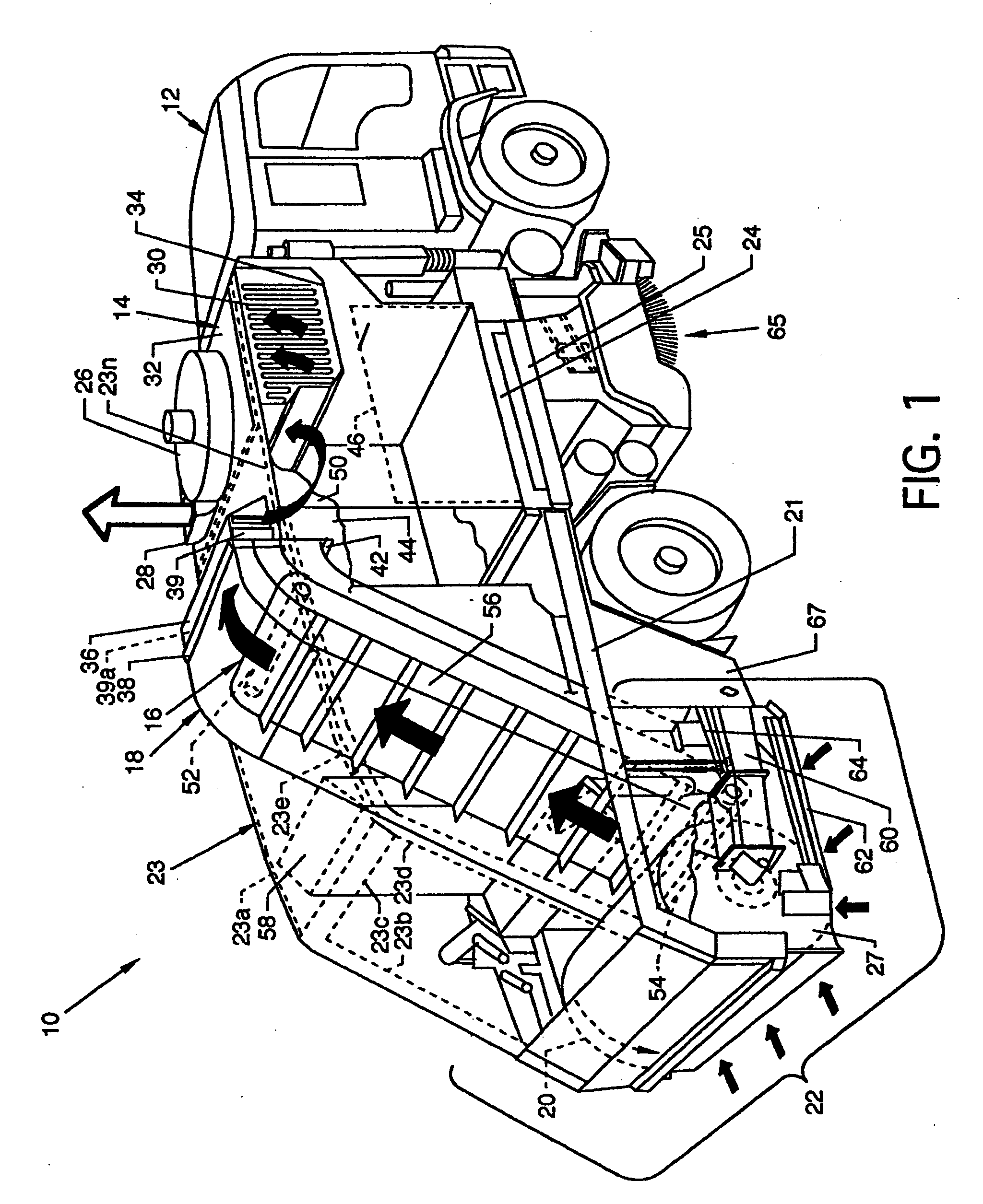
[0029]FIG. 1 illustrates a cutaway overview of the street sweeper 10, the present invention, which has vacuumized duct control. Major and other components complementary to the invention are mounted to and secured to the frame or chassis 13 of a truck 12 or are mounted elsewhere at other locations about the invention. Major illustrated components of the invention include a hopper 14, a conveyor mechanism 16, a conveyor housing 18, a rotary broom 20 and a rotary broom chamber 22 which are arranged and mounted to the chassis 13 of the truck 12 or other frameworks in a position rearward of the street sweeper rear axle 17. Rearwardly extending frameworks 21 and 21a (FIG. 3) mount and secure to the chassis 13 of the truck 12 to accommodate a portion of the components of the invention. A superstructure framework 23 including a plurality of framework members 23a-23n is shown partially and generally in dashed lines extending upwardly and forwardly from the frameworks 21 and 21a to serve as s...


PUM


Abstract

A street sweeper with vacuumized dust control where a rotary broom chamber surrounds a rotary broom. The rotary broom chamber connects by a conveyor housing containing a conveyor mechanism to a hopper having a powered fan and a filter. A vacuum or low pressure is created within the hopper which communicates through the conveyor housing to the rotary broom chamber which creates an airflow therebetween which carries dust or other light debris to a filter which filters out the dust particles or other light debris. The conveyor housing and other components are positionable to accommodate various modes of operation.

Description

CROSS REFERENCES TO RELATED APPLICATIONS [0001] None. BACKGROUND OF THE INVENTION [0002] 1. Field of the Invention [0003] The present invention is for a street cleaning device, and, more particularly, pertains to a street sweeper with vacuumized dust control. [0004] 2. Description of the Prior Art [0005] Prior art street sweeper devices are often built on and about custom chassis not generally suited for economy of speed or having attributes geared toward desirable roadability qualities. Often such street sweepers include rotary sweeper brooms placed between the front wheel assemblies and special rear wheel drive or axle assemblies beneath a configured framework in an area often otherwise reserved for drive shafts and other framework members in conventional chassis, such as used for conventional trucks. Street sweepers utilizing truck chassis are also used for mounting of street sweeper components and are utilized for greater roadability and transport speed suitable for highway use....

Claims


Application Information

Patent Timeline
Patent Type & Authority Applications(United States)
IPC IPC(8): E01H1/08E01H1/04
CPCE01H1/042E01H1/0854E01H1/0845
Inventor ENGEL, GREGORY J.BOOMGAARDEN, STEVEN L.
Owner ENGEL GREGORY J
Why Eureka
Try Eureka