Load cell attachment structure

a technology of loading cell and attachment structure, which is applied in the direction of instruments, screws, force/torque/work measurement apparatus, etc., can solve the problem that the loading cell b>100/b> cannot accurately measure the load, and achieve the effect of reducing the quantity of parts and time in assembling

Active Publication Date: 2006-03-09
TS TECH CO LTD +1
View PDF13 Cites 53 Cited by
  • Summary
  • Abstract
  • Description
  • Claims
  • Application Information

AI Technical Summary

Benefits of technology

[0008] It is therefore an object of the invention to provide a load cell attachment structure capable of preventing a load cell from sensing undesired loads which are caused by warp or a incline of the attachment plate, and as a result, load cell can measure loads accurately.
[0012] According to the present invention, a clearance which absorbs the wrap or incline of the attachment plate is appropriately formed between the washer part and the second fastening part by the collar part. In addition, the fastening force which is introduced through the collar part is dispersed on the load sensing part evenly, by the washer part. Therefore, the load cell does not sense an undesired load which is caused by the warp or the incline of the attachment plate, and the fastening force. As a result, it is possible to measure loads which act on the load sensing part exactly.
[0015] According to the present invention, since the collar part is formed as a single body with the washer part, it is possible to reduce quantity of parts and time in assembling.
[0017] According to the present invention, a clearance which absorbs the wrap or incline of the attachment plate is appropriately formed between the washer part and the second fastening part by the collar part. In addition, the fastening force which is introduced through the collar part is dispersed on the load sensing part evenly by the washer part. Therefore, the load cell does not sense an undesired load which is caused by the warp or incline of the attachment plate, and dispersion of initial values of the load cell, which is caused by difference in fastening torque is not caused. As a result, it is possible to measure loads which act on the load sensing part exactly.
[0020] According to the present invention, since the collar part is formed as a single body with the washer part, it is possible to reduce the quantity of parts and time in assembling.

Problems solved by technology

As a result, the load cell 100 cannot measure loads accurately.

Method used


Image

  • Load cell attachment structure
  • Load cell attachment structure
  • Load cell attachment structure

Examples


Embodiment Construction

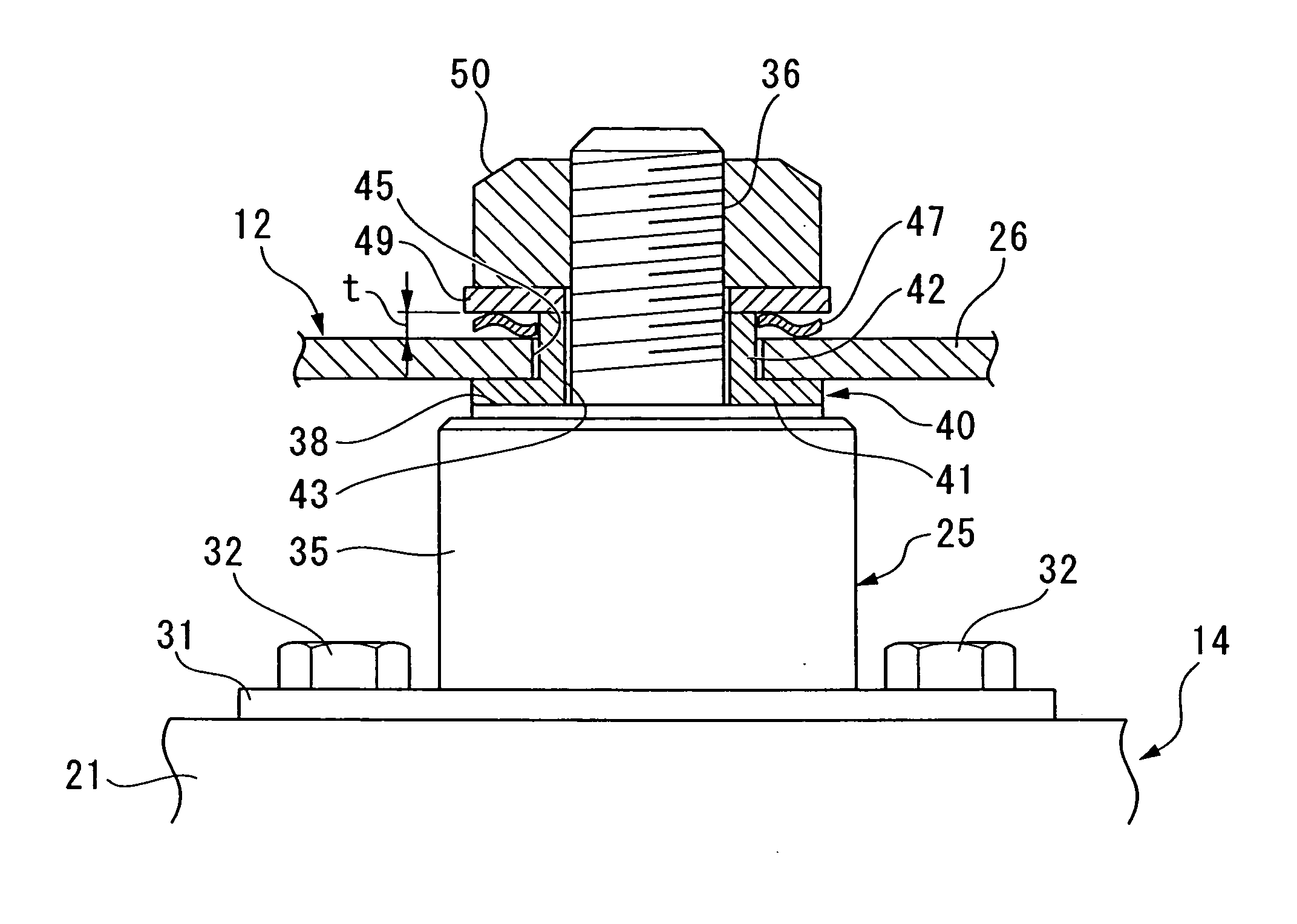
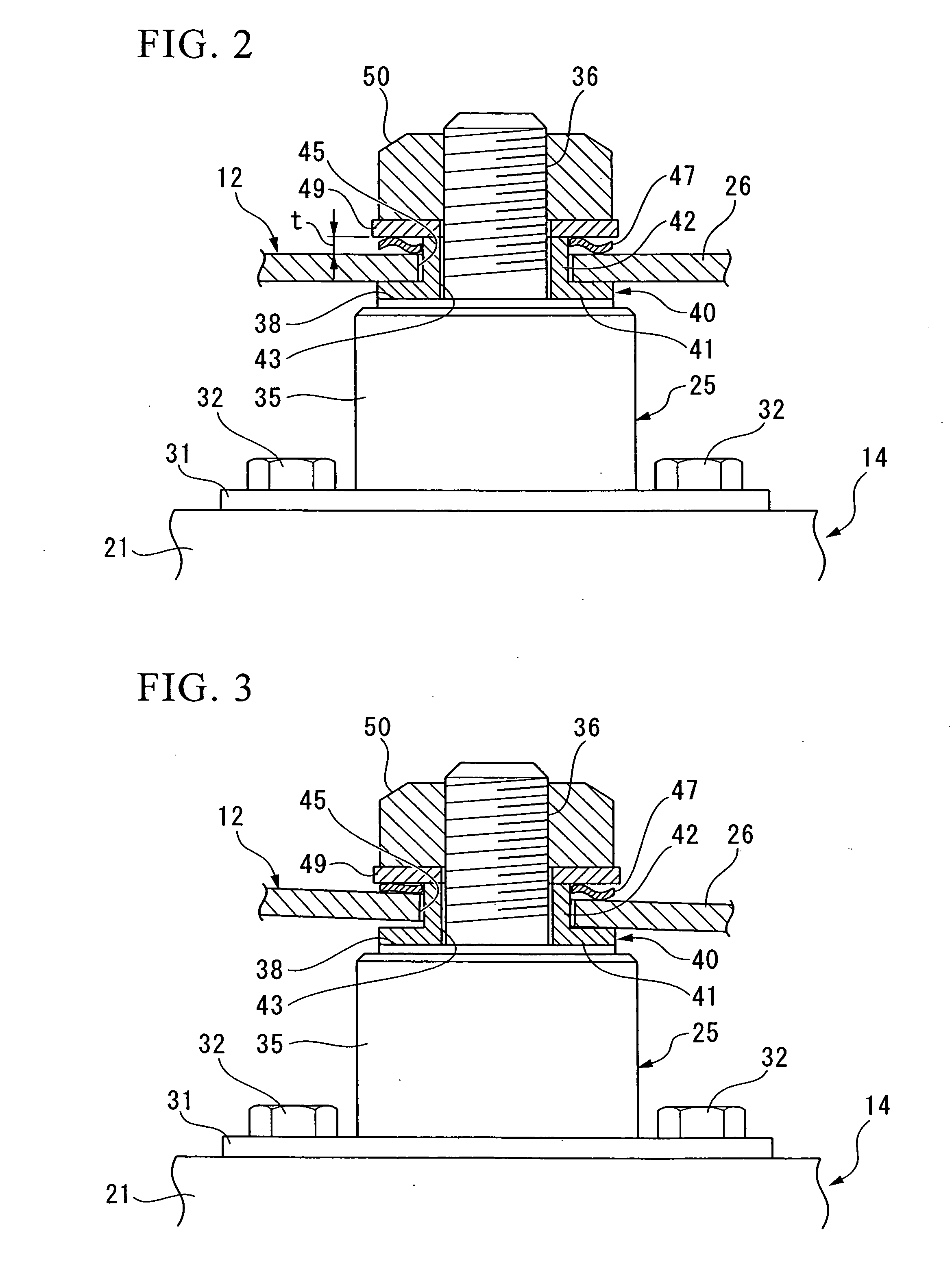
[0029] A description is given below of a load cell attachment structure according to one embodiment of the present invention with reference to the drawings.

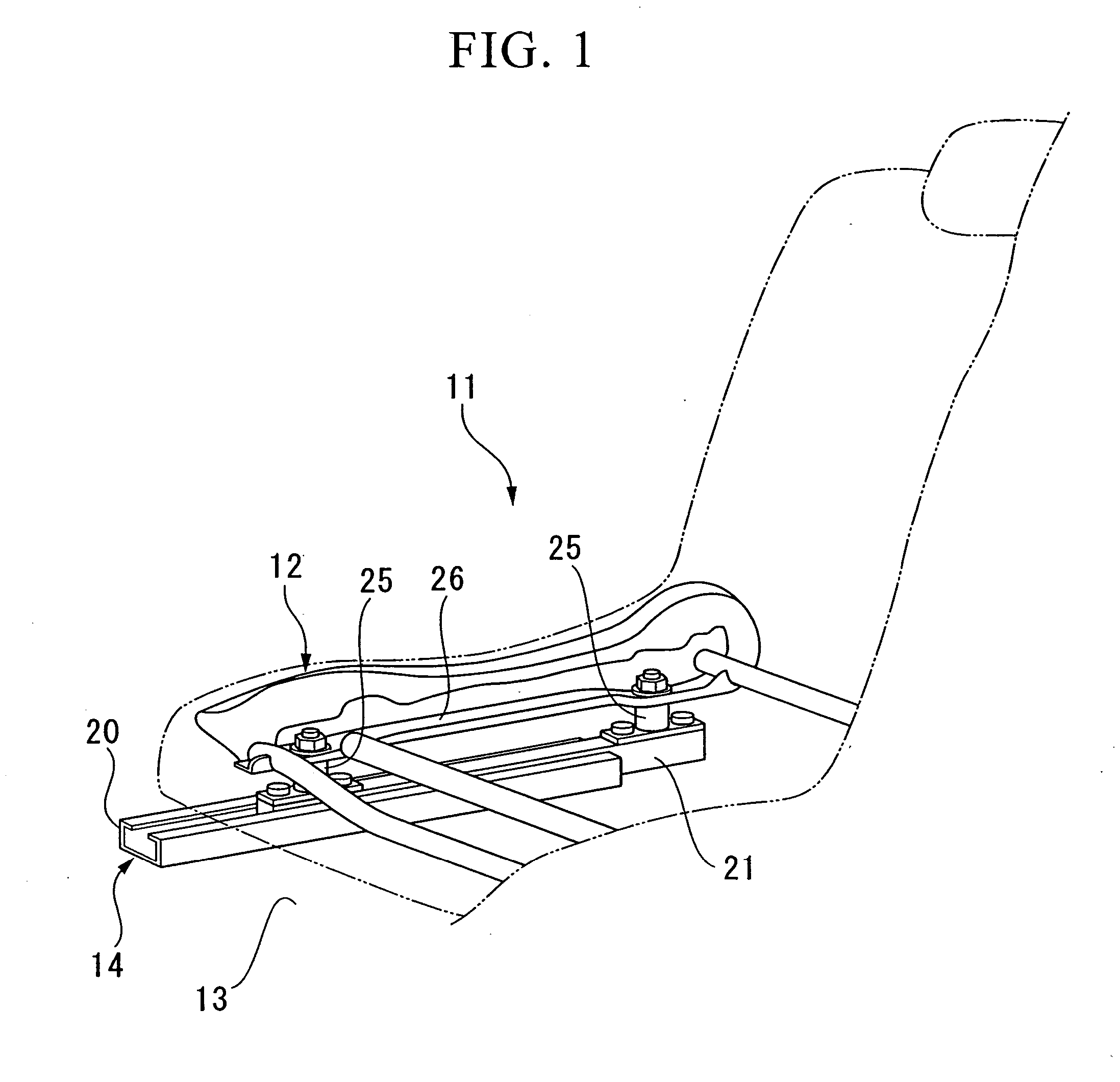
[0030]FIG. 1 shows the right half side of an occupant's seat 11 of a vehicle. A seat frame 11 which composes a skeletal structure of the seat 11 is supported on a pair of seat rails 14 so as to be capable of sliding in the lengthwise direction of the vehicle. The seat rails 14 are spaced apart from each other in the widthwise direction of the vehicle, and are fixed on a floor panel 13 of the vehicle. Note that, only one of the pair of seat rails 14 is shown in FIG. 1.

[0031] The seat rail 14 is composed of a rail main body 20 and a slider 21. The rail main body 20 extends along the lengthwise direction of the vehicle, and is fixed on the floor panel 13. The slider 21 extends along the lengthwise direction of the vehicle, and is supported on the rail main body 20 so as to be capable of sliding in the lengthwise direction of the v...


PUM

PropertyMeasurementUnit
thicknessaaaaaaaaaa
fastening forceaaaaaaaaaa
drift forceaaaaaaaaaa

Abstract

This load cell attachment structure includes a male screw which is formed on a load sensing part of the load cell, a nut which attaches the load cell to the attachment plate by engaging with the male screw, and a wave washer which is disposed between the attachment plate and the nut.

Description

BACKGROUND OF THE INVENTION [0001] 1. Field of the Invention [0002] The present invention relates to a load cell attachment structure. [0003] Priority is claimed on Japanese Patent Application No. 2004-259502, filed Sep. 7, 2004, and on Japanese Patent Application No. 2004-259503, filed Sep. 7, 2004, the content of which is incorporated herein by reference. [0004] 2. Description of Related Art [0005] In order to control operating and the like of an air bag system when a collision of a vehicle happens, a load cell which measures load acting on a seat is mounted on the vehicle. Then, it is determined whether an occupant is seated or not, and whether the occupant who is seated is an adult or a child, and the like. [0006] For example, there is a system which includes stud bolts projecting above, which is disposed on the front and rear of sliders of bilateral seat rails, a plate member which is fixed on the stud bolts and a seat frame. One end of the plate member is fixed on a tip of the...

Claims


Application Information

Patent Timeline
Patent Type & Authority Applications(United States)
IPC IPC(8): G01N3/02
CPCG01N2203/0676G01N3/02
Inventor FURUKAWA, TAKASHIKUMAKIRI, NAOTAKAKOJIMA, MIKIHITOYOSHIFUKU, MASASHIYAMAZAKI, TATSUYASHINDO, TOYOHIKONISHIDE, HARUTOMI
Owner TS TECH CO LTD
Why Eureka
Try Eureka