Anvil for a rotary cutting unit and a rotary cutting unit having such anvil

a technology of rotary cutting unit and anvil, which is applied in the direction of saw chains, manufacturing tools, stock shearing machines, etc., can solve the problems of bending of anvil, rotary cutters suffer from drawbacks, and parts of the knife members in the axial center of the rotary cutting drum do not have the rotary cutting drum, so as to increase the reliability and the life of the anvil

Active Publication Date: 2006-03-09
HYPERION MATERIALS & TECH SWEDEN AB
View PDF16 Cites 24 Cited by
  • Summary
  • Abstract
  • Description
  • Claims
  • Application Information

AI Technical Summary

Benefits of technology

[0011] Objects of the invention are to increase the reliability and the life time of the anvil.

Problems solved by technology

The described rotary cutter however suffers from the drawback that the portions of the knife members in the axial center of the rotary cutting drum do not cut as precisely as the portions of the knife members closer to the axial periphery thereof.
This is due to the fact that the rotary cutting drum exerts a pressure onto the anvil surface via the abutment members, thereby causing the anvil to be bent.
Such a rotary cutter not only suffers from the drawback described above, but also in that it has a long axial extension, causing the anvil drum and the rotary cutting drum to also be bent by gravity, i.e. the longer and heavier the anvil, the more it will be bent negatively by gravity that will add to the described effect.

Method used


Image

  • Anvil for a rotary cutting unit and a rotary cutting unit having such anvil
  • Anvil for a rotary cutting unit and a rotary cutting unit having such anvil
  • Anvil for a rotary cutting unit and a rotary cutting unit having such anvil

Examples


first embodiment

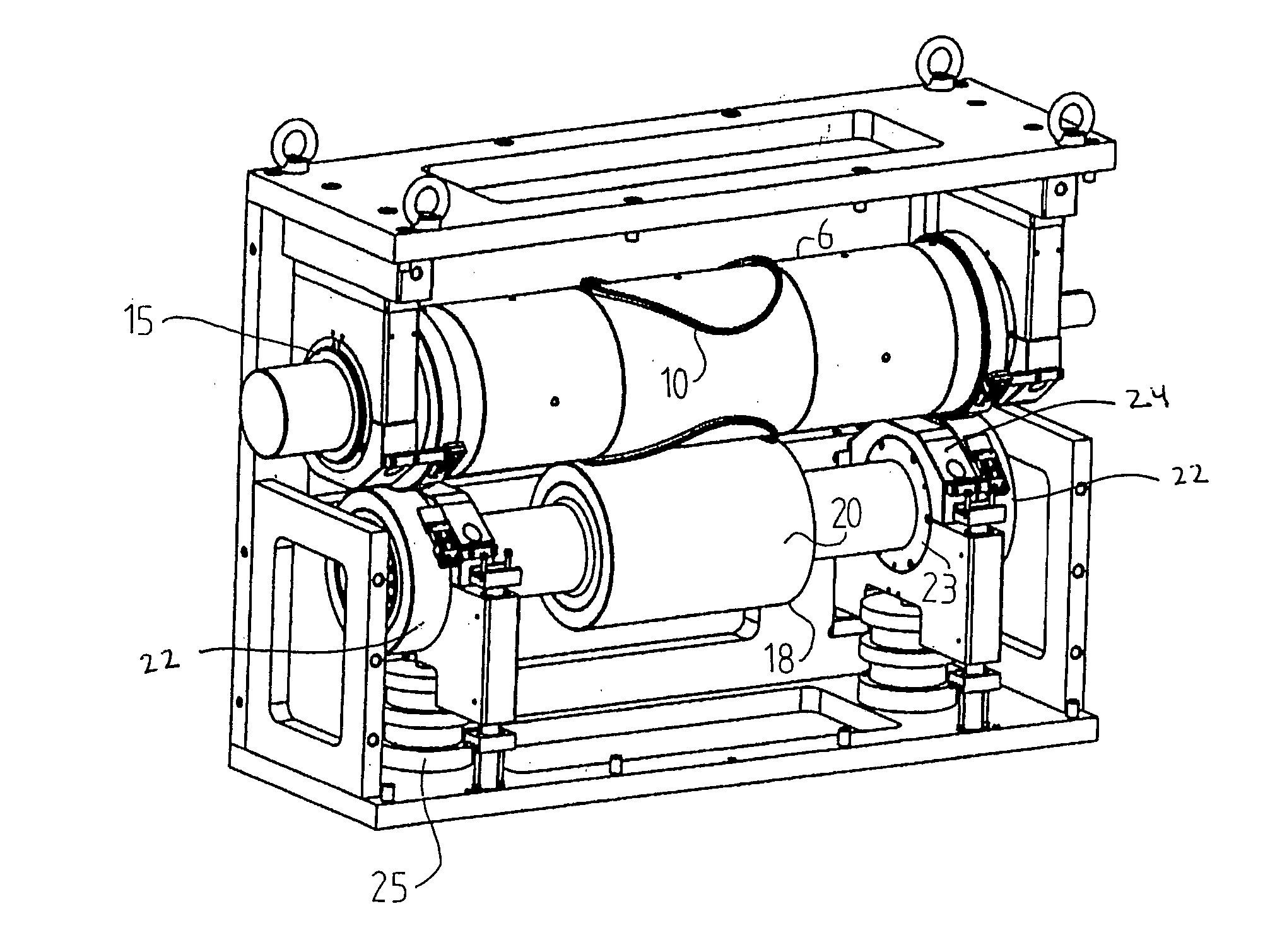
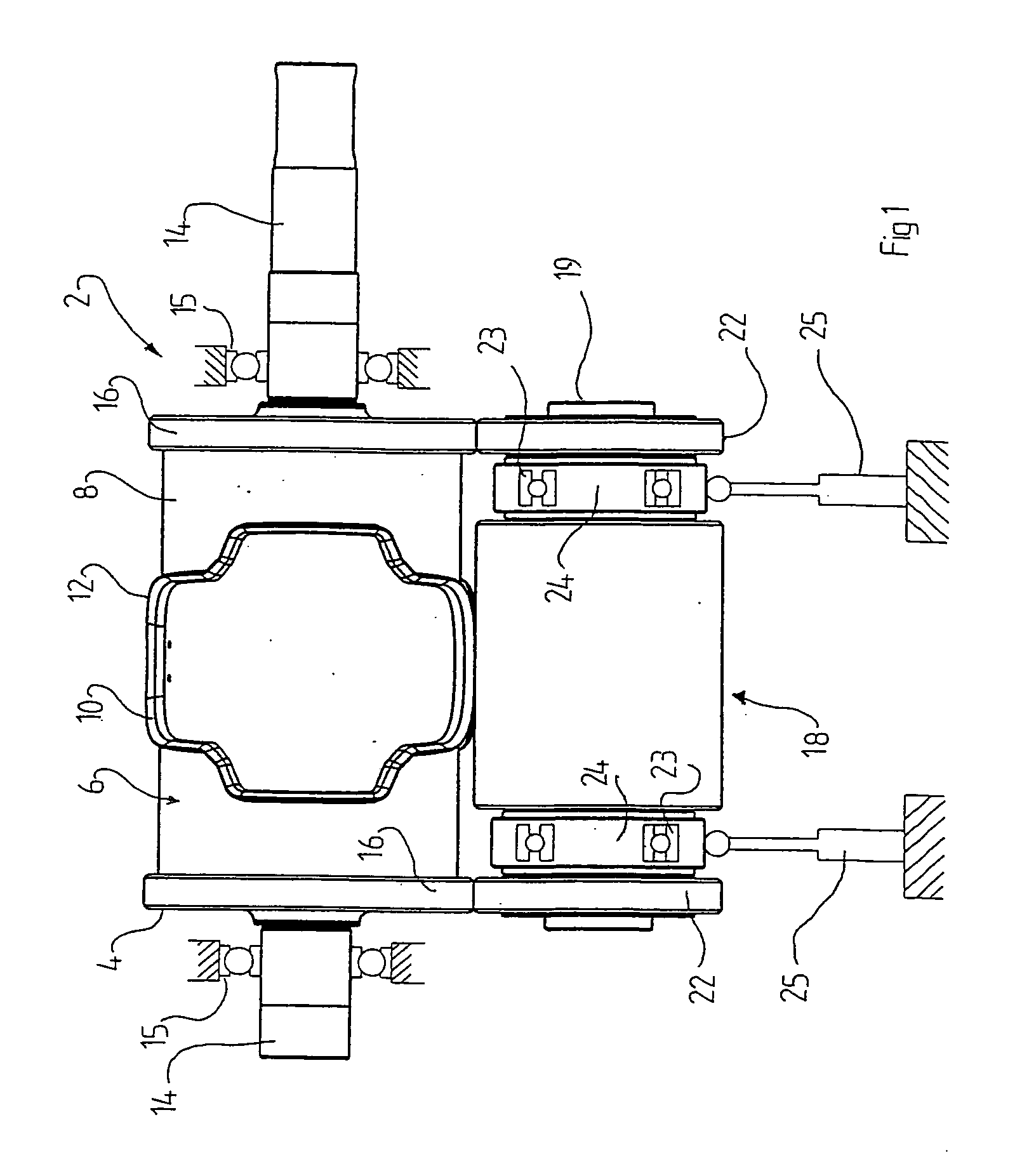
[0026]FIG. 1 shows a rotary cutting unit 2 according to the invention. A rotary cutter 4 is provided with a substantially circular-cylindrical hollow or solid body 6 having a cylindrical surface 8 and at least one knife member 10 protruding from the surface 8. The radially peripheral part 12 of said knife member 10 has a diameter larger than that of said surface 8. The rotary cutter 4 is arranged on or is an integral part of an arbour 14 extending axially from each side of the rotary cutter 4 and being supported in bearings 15. Axially on each side of said surface 8, a pair of annular abutment members 16 are provided. The abutment members 16 have a diameter larger than that of said surface 8, in order to allow abutment against an anvil 18.

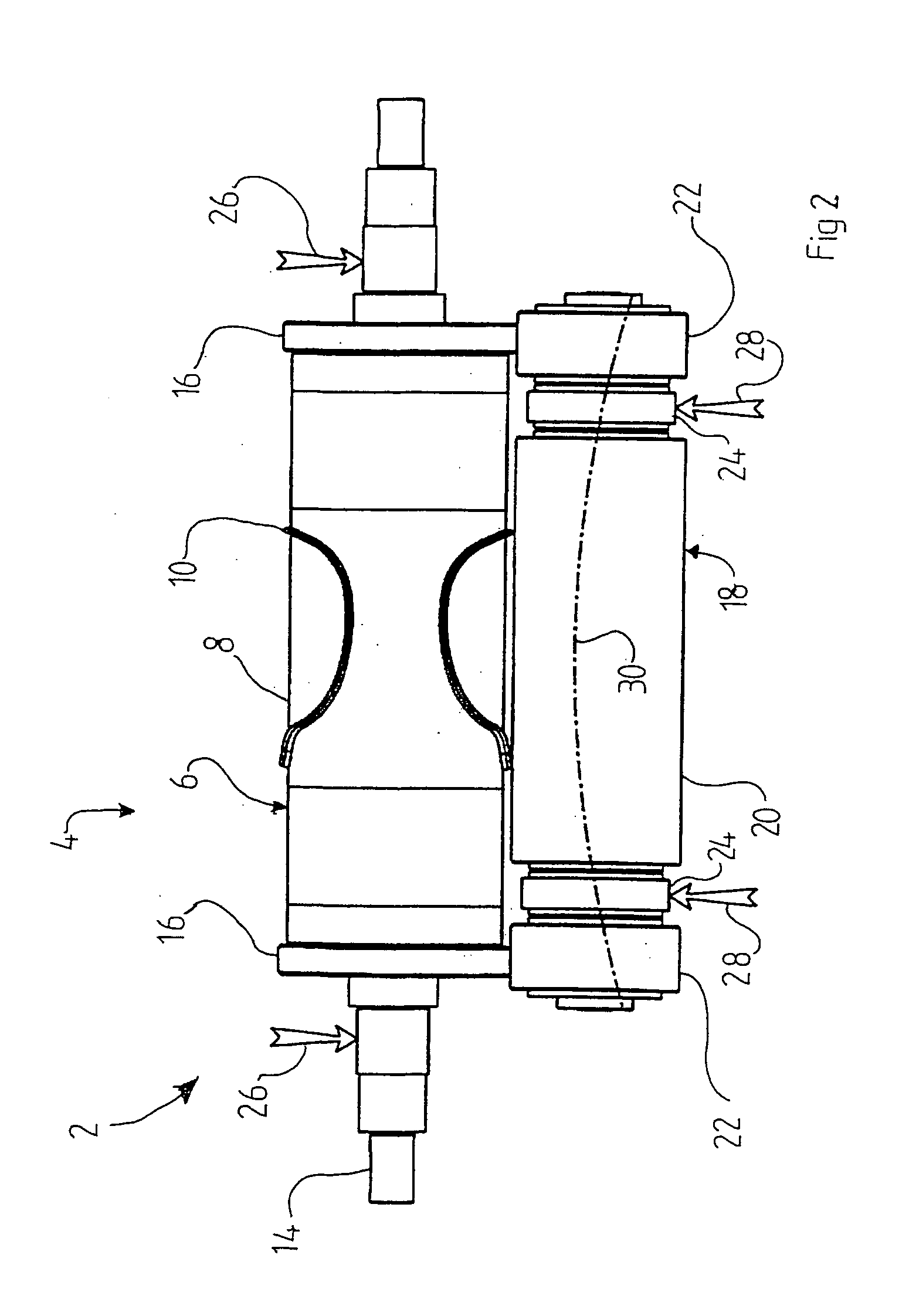
[0027] The anvil 18 includes an axle 19, an anvil portion 20 and a pair of load transmitting portions 22. The anvil portion 20 is adapted to cooperate with the knife member 10 of the rotary cutter 6, whereas the load transmitting portions 22 are ad...

second embodiment

[0034]FIG. 3 shows a rotary cutting unit. The anvil and the rotary cutter drums are long and are even more affected by gravity such that they are bent towards the ground. However, when the load transmitting portions 22 exert pressure on the abutments members 16, the anvil 18 will be bent towards the rotary cutter 6. Thus, when the pressure has been adjusted such that the line 30 (see FIG. 2) is straight, the cutting properties will be substantially equal over the whole extension of the knife members 10.

[0035] Thus, by exerting pressure 28 on the load receiving members 24, it will be possible to utilise also such a centrally disposed knife member.

[0036] Alternatively, a knife member on a long rotary cutting drum may extend substantially from one side to the other of the cutting drum, with maintained cutting properties.

third embodiment

[0037]FIG. 4 shows a rotary cutting unit 2 having a rotary cutter 6 with a pair of knife members 10 arranged axially separated. The anvil is divided into two separate anvil portions 20 corresponding to said knife members.


PUM

PropertyMeasurementUnit
forceaaaaaaaaaa
weightaaaaaaaaaa
diameteraaaaaaaaaa

Abstract

A rotary cutting unit includes a rotary cutter overlying a rotatable anvil. The anvil includes an axle, at least one anvil portion adapted to co-operate with a knife member of a rotary cutter, and a pair of load transmitting portions adapted to abut a pair of abutment members of the rotary cutter. The pair of load transmitting portions are arranged on each side of the anvil portion. A load receiving member is provided between each load transmitting portion and the anvil portion. Each of the load receiving members is connected to the axle via a bearing. Fluid cylinders apply upward forces to the load receiving members, wherein the total upward force exceeds the weight of the anvil.

Description

[0001] The present application claims priority under 35 U.S.C. § 119 to patent application Ser. No. 0401735-6 filed in Sweden on Jul. 2, 2004. TECHNICAL BACKGROUND OF THE INVENTION [0002] The present invention relates to a rotatable anvil for a rotary cutting unit, comprising an axle, at least one anvil portion adapted to cooperate with a knife member of a rotary cutter and a pair of load transmitting portions adapted to abut a pair of abutment members of said rotary cutter, said pair of load transmitting portions being arranged on each side of said anvil portion. [0003] The invention also relates to a rotary cutting unit comprising a rotary cutter and such a rotatable anvil. [0004] Such a rotary cutting unit is known from US-B-6 244 148, and comprises a rotary cutter in working relationship with a rotary anvil. The rotary cutter is provided with a substantially circular-cylindrical body having a cylindrical cutting surface and at least one knife member protruding from said surface,...

Claims


Application Information

Patent Timeline
Patent Type & Authority Applications(United States)
IPC IPC(8): B26D1/00B26D7/20B26D7/26
CPCB26D7/20B26D2007/202B26D7/265B26D7/2628Y10T83/4838Y10T83/04Y10T83/4833Y10T83/9312Y10T83/7855B26D1/40B26D7/26B26F1/38B26F1/384
Inventor GRENIER, GILBERTHARSTE, DIRK
Owner HYPERION MATERIALS & TECH SWEDEN AB
Why Eureka
Try Eureka