
Method and system of inertia friction welding

a technology of friction welding and friction, applied in the field of method and system of inertia friction welding, can solve problems such as production welds

Active Publication Date: 2006-03-09
MFG TECH INC
View PDF6 Cites 7 Cited by
  • Summary
  • Abstract
  • Description
  • Claims
  • Application Information

AI Technical Summary

Benefits of technology

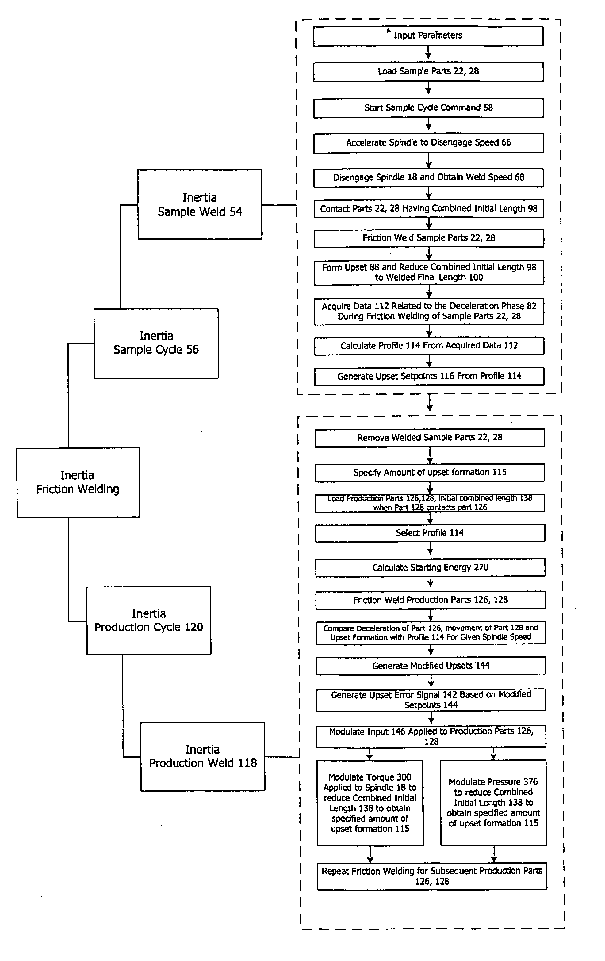
[0013] A further object of the present invention is to provide an inertia friction welding process that is capable of producing a welded part of predetermined final length by achieving a targeted upset formation during the friction welding process.
[0021] The presently described process control system provides a unique extension of known upset control techniques. Use of the inventive process control system forming the present invention enables the welding process to produce a friction weld with any targeted upset, not merely duplicating the upset of a prior sample weld. Thus, the present invention allows precise control and targeting of either the final upset or the final welded part length of the finished product.

Problems solved by technology

The pair of production parts are then inertia friction welded together resulting in rotational deceleration of the spindle, movement of the slide toward the spindle and contact between the one production part and the other production part causing upset formation and resulting in formation of a production weld.

Method used


Image

  • Method and system of inertia friction welding
  • Method and system of inertia friction welding
  • Method and system of inertia friction welding

Examples


Embodiment Construction

[0039] While the present disclosure may be susceptible to embodiment in different forms, there is shown in the drawings, and herein will be described in detail, embodiments with the understanding that the present description is to be considered an exemplification of the principles of the disclosure and is not intended to limit the disclosure to the details of construction and the number and arrangements of components set forth in the following description or illustrated in the drawings.

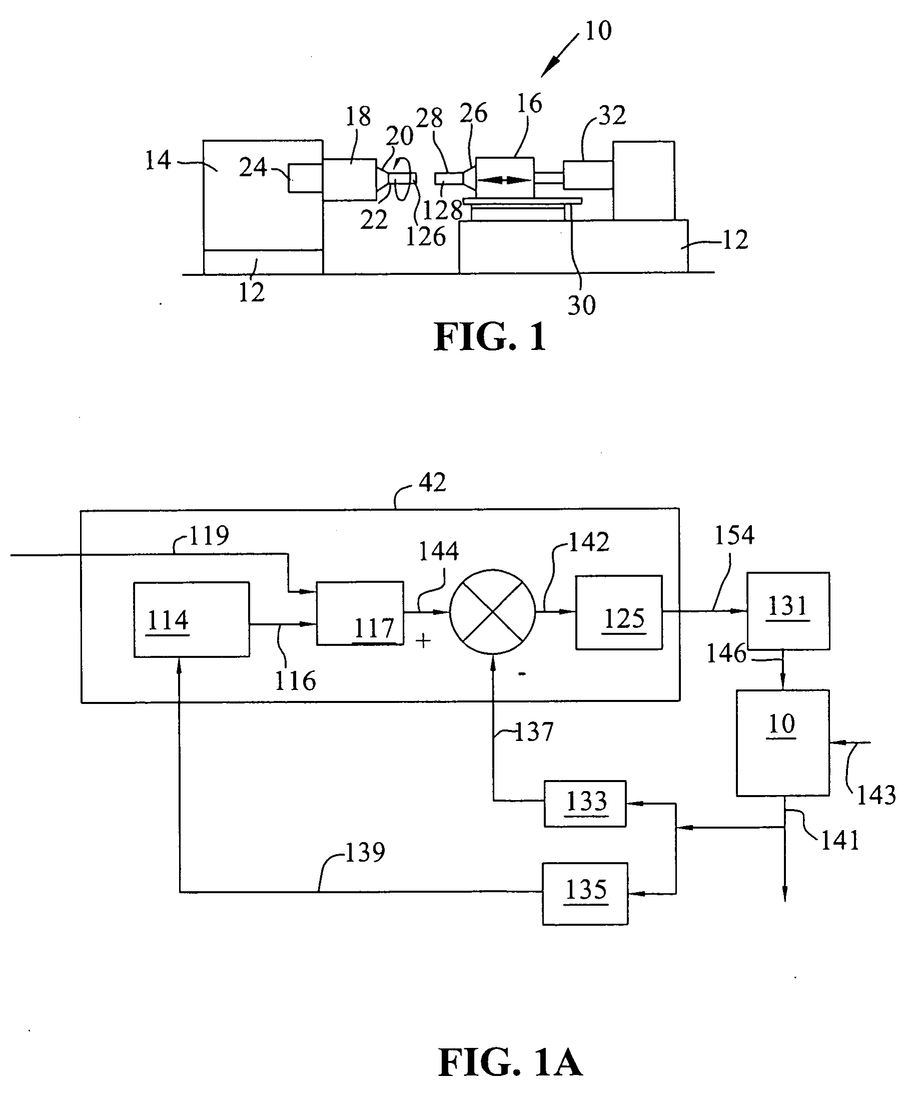
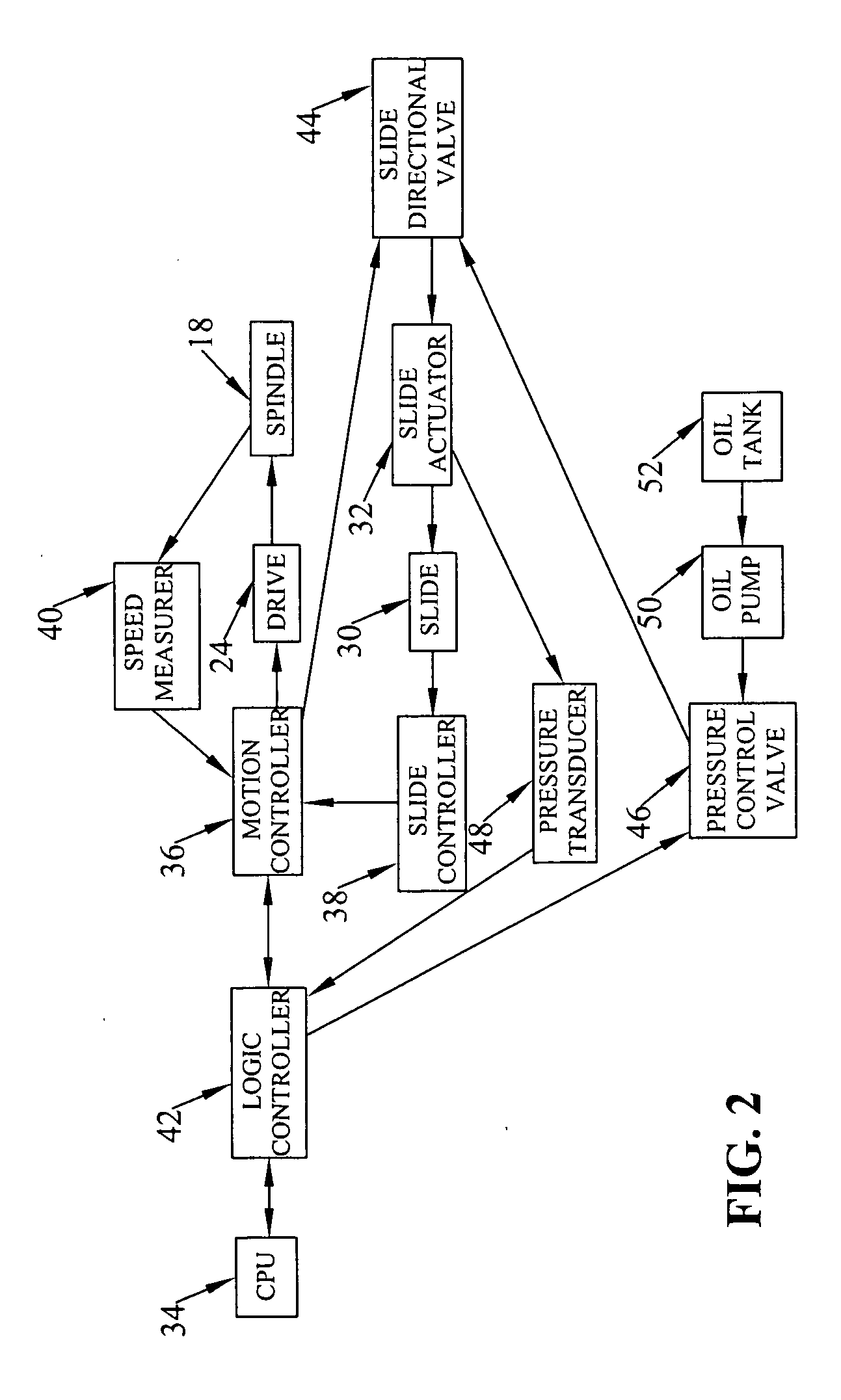
[0040]FIG. 1 illustrates a weld system 10 in the form of a friction welder 12. The friction welder 12 includes a headstock portion 14 and a tailstock portion 16 wherein the headstock portion 14 includes a spindle 18 having a rotating chuck 20 for engaging a first work part or component 22. A drive 24 such as a motor is configured to apply a torque to the spindle 18 to rotate the spindle via commands from a motion controller 36 (FIG. 2). The spindle 18 may be equipped with additional mass, such as a f...


PUM

PropertyMeasurementUnit
torqueaaaaaaaaaa
pressureaaaaaaaaaa
rotational speedaaaaaaaaaa

Abstract

A method and system of inertia friction welding that enables the production of inertia friction welds in which the final upset can be controlled to an operator specified target. The method utilizes any profile-based upset control technique, including but not limited to torque modulation and pressure (load) modulation. The method dynamically modifies the profile upset setpoints to systematically drive the upset formation to produce a weld with the targeted upset. The method and system also enables the production of inertia friction welds in which the final welded part length can be controlled to an operator specified target. The system and associated method comprises inertia friction welding a pair of sample parts to form a sample weld while acquiring data relating to the formation of the sample weld. The system and associated method also comprises inertia friction welding a pair of production parts to form a production weld using the profile data acquired during the friction welding of the pair of sample parts to achieve the predetermined upset formation.

Description

PRIORITY CLAIM [0001] This application claims priority to the U.S. Provisional Application filed on Sep. 3, 2004 having Ser. No. 60 / 607,153 to the extent permitted by law.BACKGROUND [0002] The present disclosure relates to a method and system of inertia friction welding together parts. [0003] Friction welding can be used to join similar and dissimilar metals in a short period of time compared to more conventional welding methods. Inertia friction welding is a variation of friction welding in which the energy required to make the weld is supplied primarily by stored rotational kinetic energy of the welding machine. [0004] During inertia friction welding, material from the parts is displaced or “upset” which results in a reduction of the combined length of the welded parts. Thus, the finished product length is the sum of the length of the parts before the inertia friction welding process minus the effect of the upset experienced by the parts during the inertia friction welding process...

Claims


Application Information

Patent Timeline
Patent Type & Authority Applications(United States)
IPC IPC(8): B23K20/12B23K31/02
CPCB23K20/12B23K20/121G05B2219/50235G05B2219/45146G05B2219/43074
Inventor LOVIN, JEFFADAMS, ROBERTKURUZAR, DANSPINDLER, DIETMAR
Owner MFG TECH INC
Learn More