Liquid ejection recording head

a recording head and liquid ejection technology, applied in printing and other directions, can solve the problems of difficult adjustment of the size of the droplet to accommodate the formation of high-resolution images, the difficulty of serial-type recording apparatuses ejecting droplets of different sizes, and the inability to meet the demands of high-speed printing

Inactive Publication Date: 2006-03-09
CANON KK
View PDF4 Cites 18 Cited by
  • Summary
  • Abstract
  • Description
  • Claims
  • Application Information

AI Technical Summary

Benefits of technology

[0012] The present invention is directed to a liquid ejection recording

Problems solved by technology

However, for printing rough images not requiring high resolution, such as color graphs in reports, recording heads for producing small droplets and printing high-resolution images cannot meet demands for high-speed printing, because of the large amounts of output data and time required for data transfer.
In this case, it is difficult for a serial-type recording apparatus to eject droplets of different siz

Method used


Image

  • Liquid ejection recording head
  • Liquid ejection recording head
  • Liquid ejection recording head

Examples


first embodiment

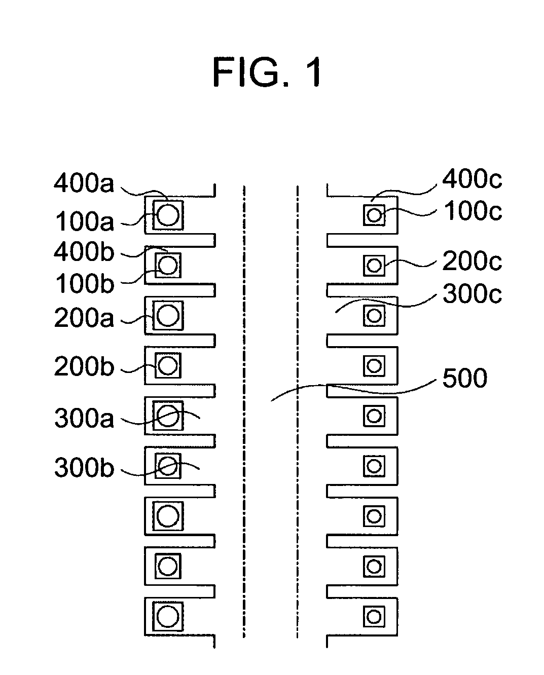
[0037]FIG. 1 is a diagram for explaining a nozzle configuration according to the first embodiment of the present invention.

[0038] A recording element of the present embodiment is provided with first nozzles 100a each having a first diameter, second nozzles 100b each having a second diameter smaller than the first diameter, and third nozzles each having a third diameter smaller than the second diameter. Droplets ejected from the first nozzles have the largest diameter, and droplets ejected from the third nozzles have the smallest diameter. Therefore, the first nozzles, the second nozzles, and the third nozzles will hereinafter be referred to as “large nozzles”, “medium nozzles”, and “small nozzles”, respectively, and droplets ejected therefrom will be referred to as “large dots”, “medium dots”, and “small dots”, respectively.

[0039] In the present embodiment, a plurality of large nozzles 100a and medium nozzles 100b are alternately arranged on the left side of an ink supply port 500...

second embodiment

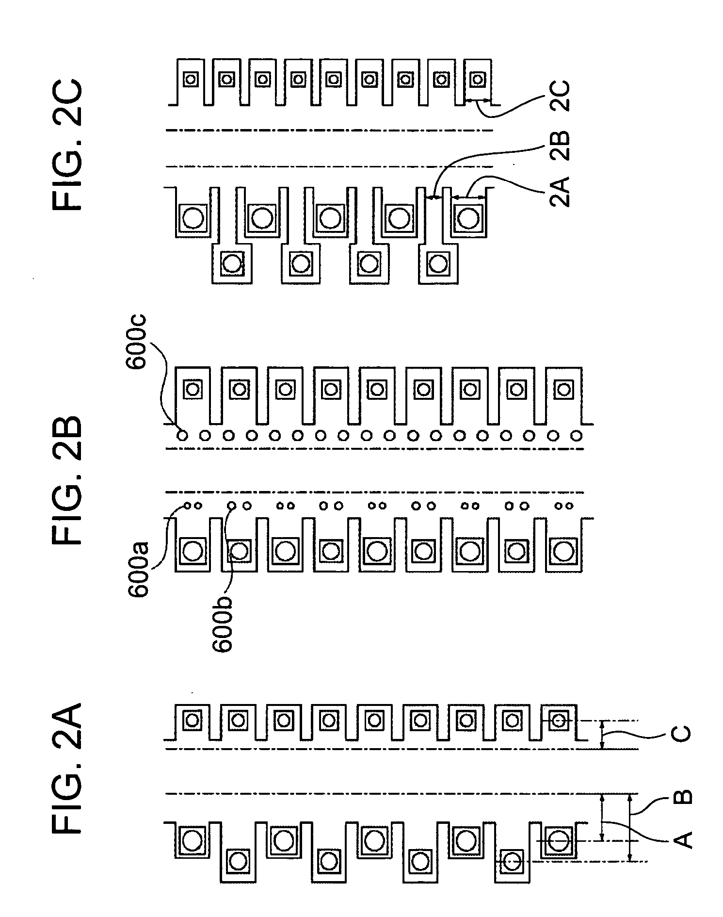
[0049]FIG. 3A is a diagram for explaining a nozzle configuration according to the second embodiment of the present invention.

[0050] In the present embodiment, a plurality of large nozzles 100a and medium nozzles 100b are alternately arranged on the left side of an ink supply port 500, while a plurality of small nozzles 100c are arranged on the right side of the ink supply port 500. The large nozzles 100a, the medium nozzles 100b, and the small nozzles 100c communicate with the ink supply port 500 via pressure chambers 400a, pressure chambers 400b, and pressure chambers 400c, and via ink channels 300a, ink channels 300b, and ink channels 300c, respectively.

[0051] In the present embodiment, the volume of droplets Va ejected from each large nozzle 100a is 10 pl, the volume of droplets Vb ejected from each medium nozzle 100b is 2.5 pl, and the volume of droplets Vc ejected from each small nozzle 100c is 1 pl. These volumes can be achieved by adjusting the sizes of the large nozzles 10...

third embodiment

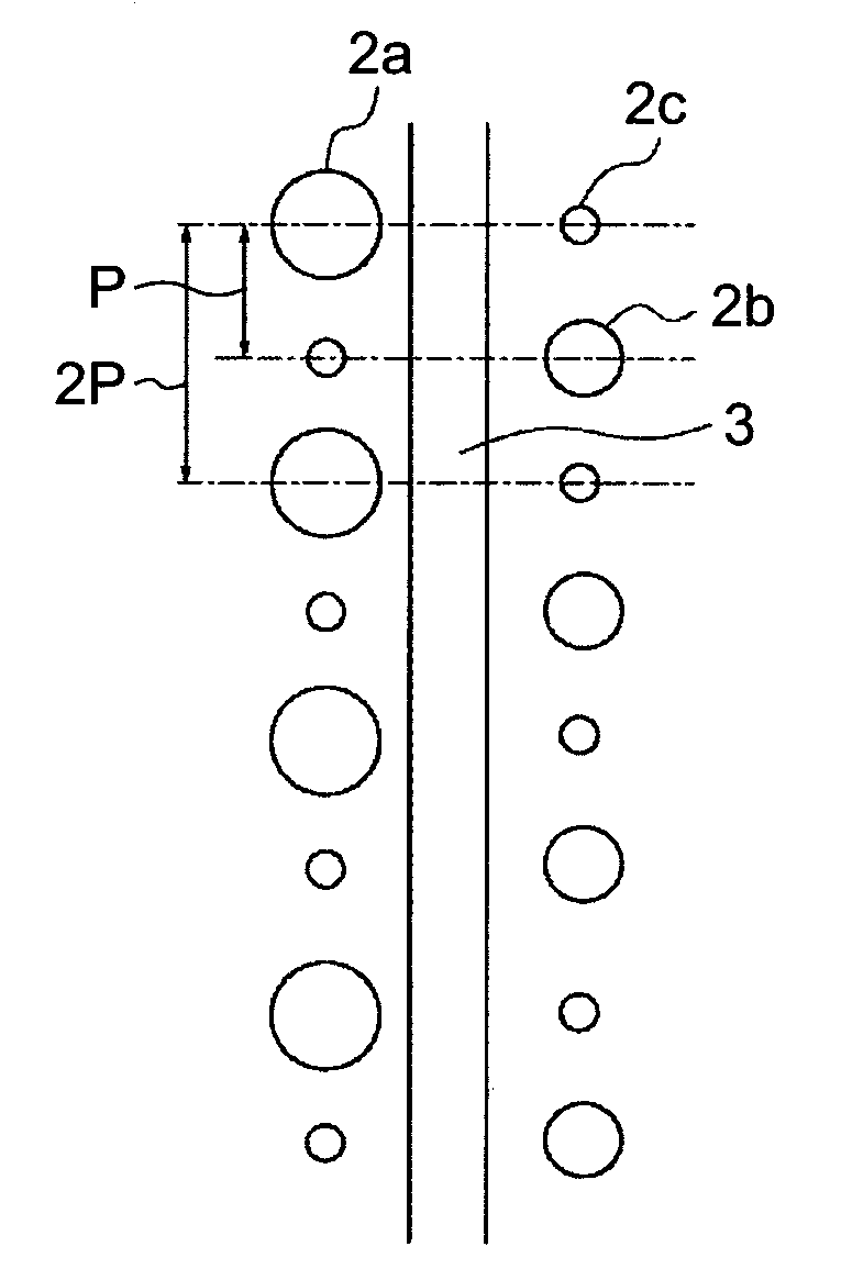
[0058]FIG. 5A shows the third embodiment of the present invention. Referring to FIG. 5A, large nozzles 2a (with pitch 2P) for 300 dpi resolution and small nozzles 2c (with pitch P) for 600 dpi resolution are arranged on the left side of an ink supply port 3. Center lines of the large nozzles 2a on the left side are aligned with corresponding center lines of the small nozzles 2c on the right side.

[0059] The volume of droplets ejected from each of the large, medium, and small nozzles varies, for example, depending on the nozzle pitch P or the physical properties of the ink. In the present embodiment, where the nozzle pitch P corresponds to a resolution of 600 dpi, the volumes of ink ejected from a large nozzle 2a, medium nozzle 2b, and small nozzle 2c are 12 pl, 4.5 pl, and 1.5 pl, respectively.

[0060] By absorption or by the application of pressure, the inkjet recording apparatus causes ink to be supplied from the ink tank (not shown) through an ink supply port 3 to the nozzles of t...


PUM


Abstract

A compact liquid ejection recording head capable of forming high-quality images at high speed includes large nozzles for ejecting large droplets, medium nozzles for ejecting medium droplets, and small nozzles for ejecting small droplets. The large nozzles are arranged on one side of an ink supply port, while the small nozzles and the medium nozzles are arranged on the other side of the ink supply port. The number of the small nozzles is larger than that of the medium nozzles, and that of the large nozzles. This allows high-quality and high-speed printing using the small nozzles, high-speed photo printing using the medium and small nozzles, and high-speed printing using the large nozzles.

Description

BACKGROUND OF THE INVENTION [0001] 1. Field of the Invention [0002] The present invention relates to liquid ejection recording heads for ejecting liquid to a recording medium, and specifically to a liquid ejection recording head for ejecting a plurality of droplets of multiple volumes to a recording medium. [0003] 2. Description of the Related Art [0004] The resolution offered by color inkjet printers using thermal inkjet technology is increasing rapidly. In particular, in recording heads for forming images, the resolution of nozzles from which droplets are ejected is increasing yearly, such as from 600 dpi to 1200 dpi. [0005] As for the size of ink droplets for forming images, in particular, color ink droplets ejected from a recording head, the size is decreasing yearly from, for example, about 15 pl to 5 pl, then to 2 pl for reducing graininess in halftones in gray-scale images, and halftones and highlights in color photo images. [0006] However, for printing rough images not requi...

Claims


Application Information

Patent Timeline
IPC IPC(8): B41J2/16
CPCB41J2/1404B41J2/15B41J2002/14403B41J2002/14387B41J2/2125
Inventor OSADA, TORACHIKAYAMANAKA, AKIHIROINOUE, TOMOYUKIMIZUTANI, MICHINARIYAMADA, HIROSHI
Owner CANON KK
Why Eureka
Try Eureka