Illuminating device and projector device

Inactive Publication Date: 2006-03-09
NIKON CORP
View PDF5 Cites 25 Cited by
  • Summary
  • Abstract
  • Description
  • Claims
  • Application Information

AI Technical Summary

Benefits of technology

[0010] A projector device to be mounted in an electronic apparatus according to a first aspect of the present invention includes a first member constituted of a thermally conductive material, at which a light emitting device is disposed; a light modulating member that modulates light originating from the light emitting device; a projection optical system that projects an image formed with the light modulated by the light modulating member; a

Problems solved by technology

However, it is necessary to supply a large electrical current to the LED in order to increase the brightness with which light is emitted

Method used


Image

  • Illuminating device and projector device
  • Illuminating device and projector device
  • Illuminating device and projector device

Examples


first embodiment

[0055] The following is an explanation of a projector device achieved in the first embodiment of the present invention, given in reference to drawings. In the first embodiment, a projector device is mounted at a portable telephone which is an electronic apparatus.

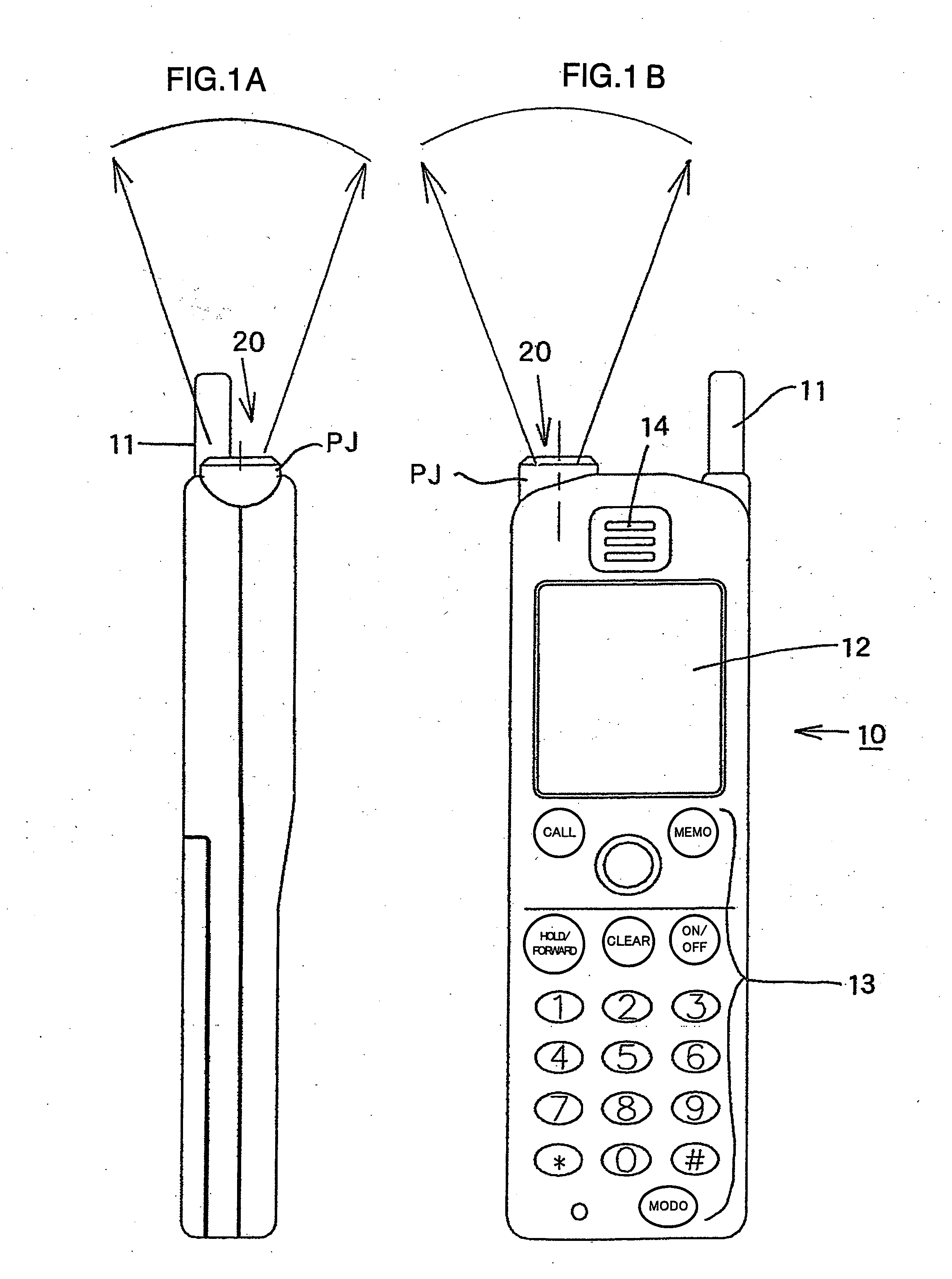
[0056]FIGS. 1A and 1B present external views of a handheld-type portable telephone equipped with a projector, achieved in the first embodiment of the present invention, with FIG. 1A presenting a side elevation and FIG. 1B presenting a front view. The portable telephone 10 includes an antenna 11, a liquid crystal display 12, an operating member 13 which includes a dial button and the like, ventilating holes 14 and a projector projecting port 20. The portable telephone 10 is used to exchange e-mail, data and the like as well as to make / receive a telephone call to / from another telephone via a base station (not shown). In addition, it is equipped with a projector device to be detailed later, which projects an image, a received...

second embodiment

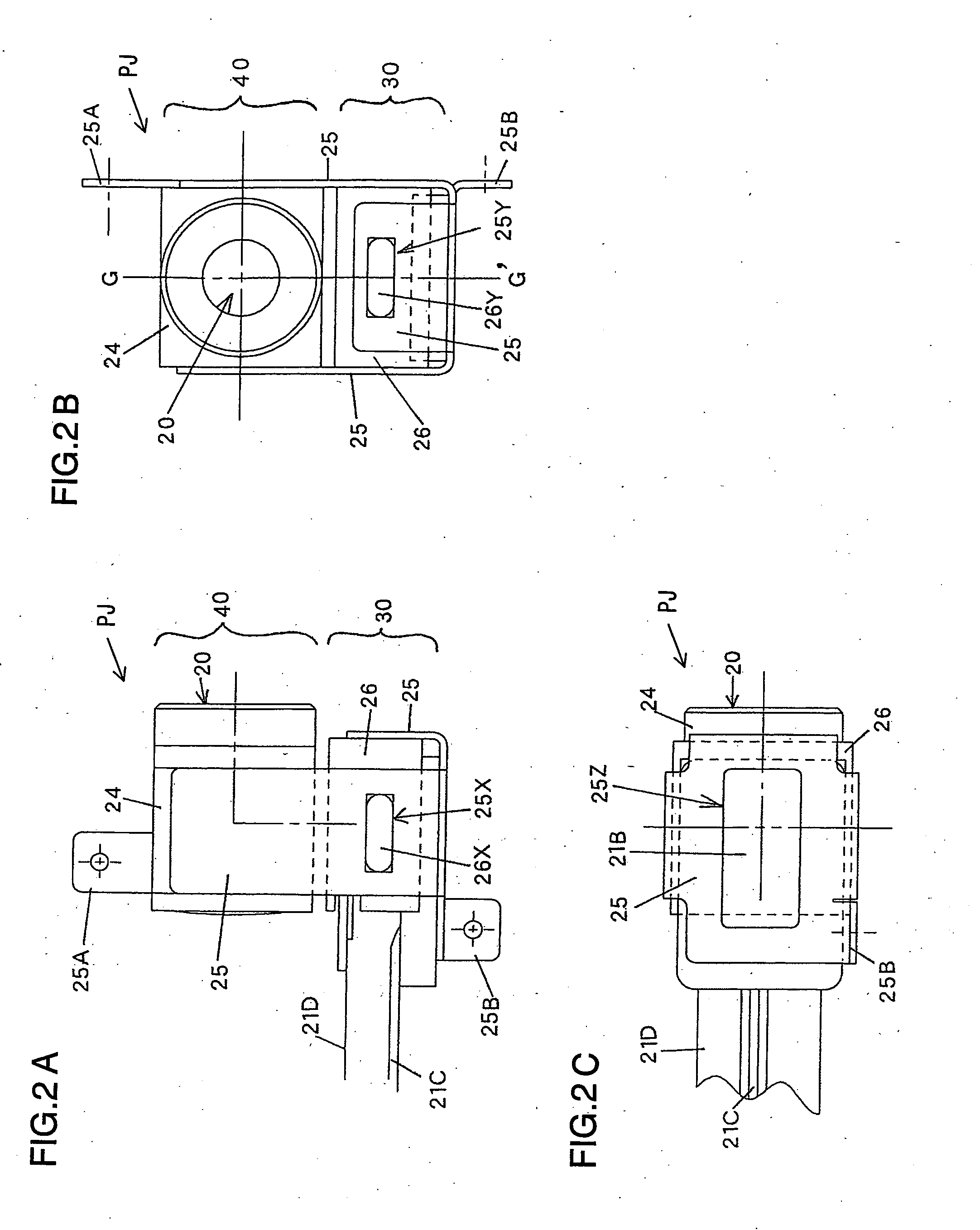
[0079]FIGS. 4A to 4E present five-view diagrams of a projector module PJ achieved in the second embodiment of the present invention, with FIG. 4A presenting a rear view, FIG. 4B presenting a bottom view, FIG. 4C presenting a left side elevation, FIG. 4D presenting a front view and FIG. 4E presenting a right side elevation. The second embodiment differs from the first embodiment in that, the optical block and the optical image forming block are constituted as a single block. The module constituted as a single block is then integrated with a locking member 125 (third member). The locking member 125 may be formed by bending a metal sheet such as an aluminum plate through a sheet metal bending process. The locking member 125 includes mounting portions 125A and 125B (mounting margins) each having formed therein a threaded retaining hole, and the projector module PJ is locked in a casing of the electronic apparatus via the mounting portions 125A and 125B.

[0080]FIG. 5 is a sectional view ...

fourth embodiment

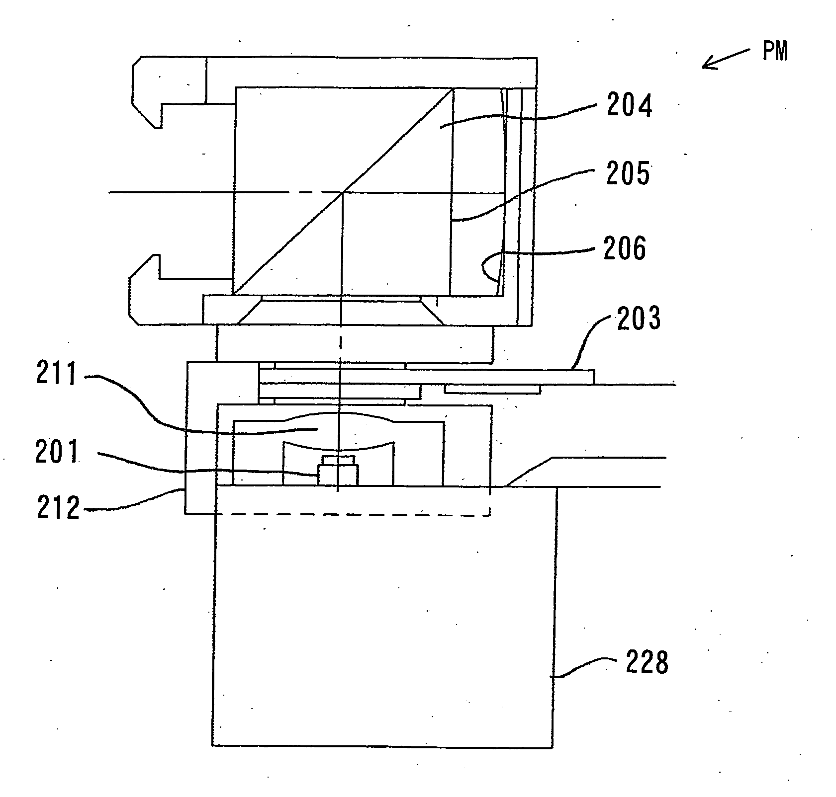
[0127] An illuminating device achieved in the fourth embodiment of the present invention is now explained in reference to FIGS. 19 and 20. The illuminating device in the fourth embodiment is constituted as a liquid crystal projector.

[0128]FIG. 19 is a front view of the liquid crystal projector achieved in the fourth embodiment and FIG. 20 is a sectional view taken along line II-II. A casing 310 of the projector is constituted of a metal material achieving a high level of thermal conductivity, e.g., die-cast aluminum. Legs 311b are disposed at the four corners of a lower surface 311a of the casing 310 so as to form a gap between a surface P of a desk or the like on which the casing 310 may be placed and the casing lower surface 311a.

[0129] The following components are housed inside the casing 310.

[0130] LEDs 301 capable of emitting very bright light, which are used as a light source, are mounted at a metal LED substrate 302. The LED substrate 302 includes a conductive circuit form...


PUM


Abstract

A projector module adopts a structure having an optical image forming block and an optical block integrated via a locking member. The optical image forming block adopts a structure achieved by disposing an aluminum substrate at which an LED is mounted and a liquid crystal panel in a casing constituted with a plastic material having low thermal conductivity. The locking member is formed by bending a metal sheet through a sheet metal bending process and the locking member is set in surface contact with the substrate. The optical block adopts a structure achieved by disposing a PBS and a reflecting member at the casing constituted with a plastic material having low thermal conductivity with a quarter-wave plate disposed at the boundary of the two members.

Description

INCORPORATION BY REFERENCE [0001] The disclosures of the following priority applications are herein incorporated by reference: [0002] Japanese Patent Application No. 2004-258466 filed Sep. 6, 2004 [0003] Japanese Patent Application No. 2004-365883 filed Dec. 17, 2004 [0004] Japanese Patent Application No. 2005-037335 filed Feb. 15, 2005 [0005] Japanese Patent Application No. 2005-063948 filed Mar. 8, 2005 BACKGROUND OF THE INVENTION [0006] 1. Field of the Invention [0007] The present invention relates to an illuminating device and a projector device that use a light emitting element as a light source. [0008] 2. Description of Related Art [0009] Japanese Laid Open Patent Publication No. 2000-194275 discloses an image display device (projector) having a liquid crystal display (LCD) constituted with a liquid crystal panel or the like and a light source for illuminating the LCD, which projects an image formed with light (modulated light) having been transmitted through the LCD. An LED w...

Claims


Application Information

Patent Timeline
IPC IPC(8): F21V29/00
CPCF21V29/004F21V33/0056F21V29/89H04M1/0272F21V29/763F21Y2101/02F21Y2115/10F21V29/74
Inventor FUJINAWA, NOBUHIRONOZAKI, HIROTAKE
Owner NIKON CORP
Why Eureka
Try Eureka