Shell and tip for hearing aid

a hearing aid and shell technology, applied in the field of hearing aids, can solve the problems of difficult to meet the fit needs of a wide range of individuals, and difficult to create a reasonable number of standardized shells configured to fit a substantial number of individuals, etc., to achieve the effect of reducing the insulation of the sound exchange, reducing the rotation of the device, and reducing the cost of acquisition

Inactive Publication Date: 2006-03-09
EARCRAFT
View PDF3 Cites 37 Cited by
  • Summary
  • Abstract
  • Description
  • Claims
  • Application Information

AI Technical Summary

Benefits of technology

[0008] It is also an object of the present invention to provide a pliable shell tip to isolate a hearing aid shell, such as the improved shell described herein, from direct contact with the interior of the user's ear at or adjacent to the point where the hearing aid extends furthest into the ear canal. It is a further object of the present invention to provide such a protective tip should be designed to minimize insulation of the sound exchange from the hearing aid equipment to the eardrum, and optionally, to enable the user to get the hearing aid out of the ear canal relatively easily. These objects are achieved through the application of a removable pliable shell tip to be described herein that fits over the operational end of the shell and spaces that end of the shell from direct contact with the user's ear canal.
[0009] The hearing aid shell of the present invention includes an ear canal entry section and an electronics retaining section, preferably forming a unitary shell. The ear canal entry section is of a first elliptical shape and then curves through a transition stage to the electronics retaining section that is of a second elliptical shape. A first side of the shell has a substantially continuous curvature whereas a second side, the one that is closer to the user's head when the hearing aid is in place, has three curvatures. The first curvature of the second side forms part of the ear canal entry section, the second curvature forms part of the transition stage, and the third curvature forms part of the electronics retaining section. Prior hearing aid shells, such as the one shown in the Weeks patent incorporated herein by reference, transition abruptly from the ear opening contact portion to the electronics retaining portion. The shell of the present invention transitions smoothly through the three different curvatures, in substantial conformance with most ear shapes. Further, the end of the shell that is designed to be positioned closest to the user's eardrum is also preferably of an elliptical shape to assist in a snug fit within the ear canal and to minimize rotation of the device.
[0010] The hearing aid shell tip of the present inventio...

Problems solved by technology

While a custom fabricated hearing aid shell ensures the user will have the best fit of the aid within the ear canal, it is the most costly and time consuming to obtain.
Therefore, it may be difficult to...

Method used


Image

  • Shell and tip for hearing aid
  • Shell and tip for hearing aid
  • Shell and tip for hearing aid

Examples


Embodiment Construction

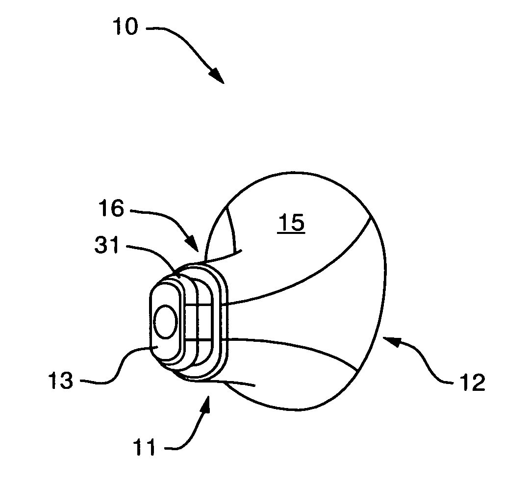
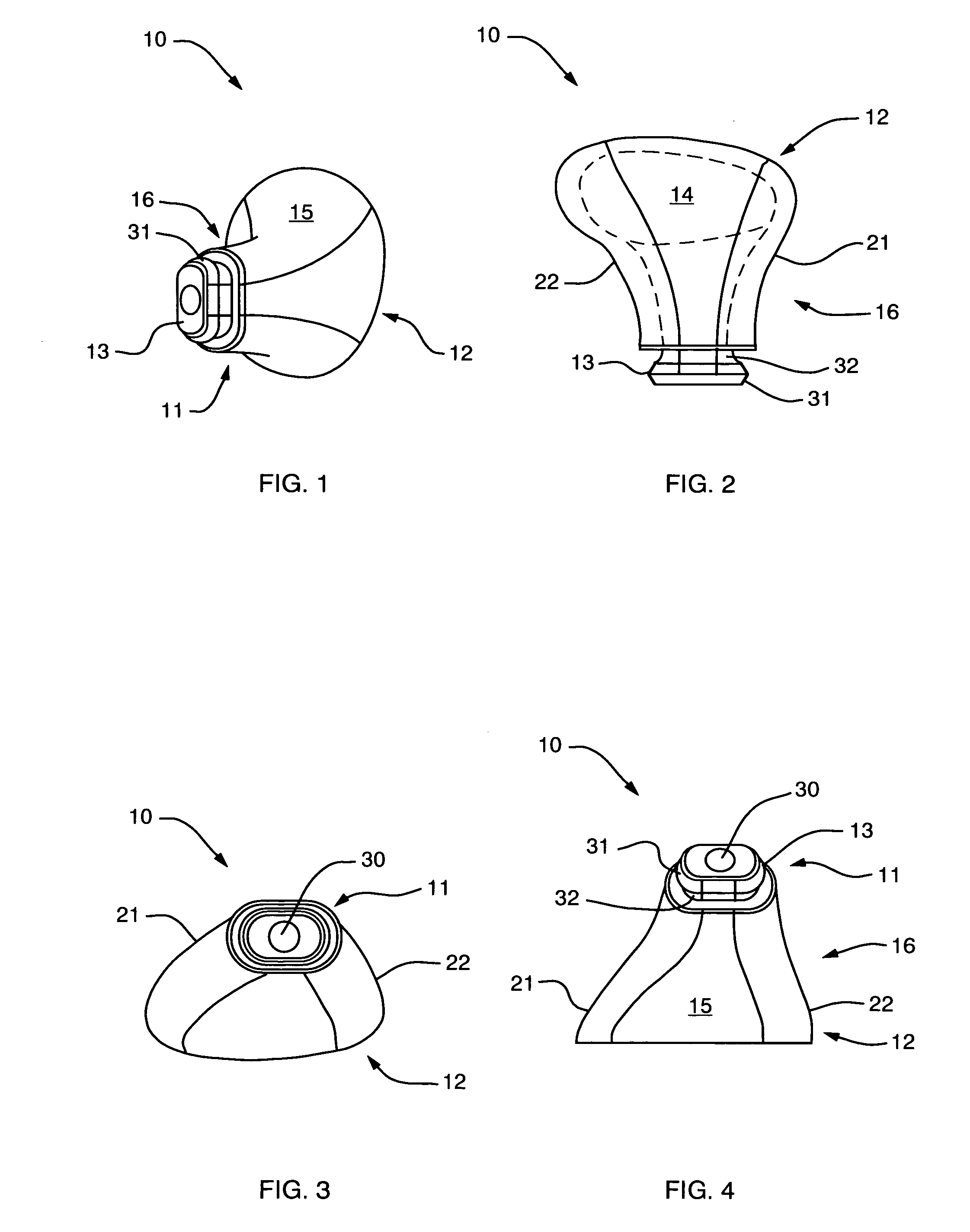
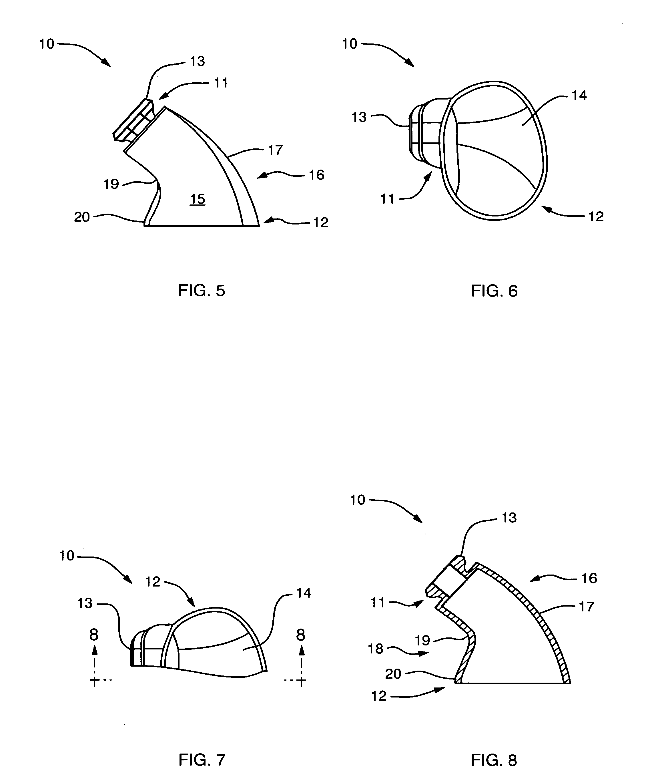
[0026] A hearing aid shell 10 of the present invention is shown in FIGS. 1-8. The hearing aid shell 10 shown in FIGS. 1-8 is a right-ear version thereof. It is to be understood that a left-ear version would be a mirror image of the right-ear version. Therefore, the following detailed description of the shell 10 is applicable to both right-ear and left-ear versions. The shell 10 includes a front end 11 and a back end 12. The front end 11 is designed for insertion into the ear canal. It includes a head section 13 for receiving and retaining thereon an optional removable hearing aid shell tip to be described herein. The shell tip is designed to separate the head section 13 from direct physical contact with the interior of the ear so as to reduce wax buildup on the front end 11, and to aid in establishing a snug fit in the ear. The back end 12 includes a port 14 for insertion into a shell body 15 the electronics required to effect the amplification of sound entering a hearing aid includ...


PUM


Abstract

A hearing aid shell and tip for retaining therein hearing aid electronics. The shell body is shaped to conform with the inside shape of the ear to reduce rotation when positioned therein. A head section of the shell positioned deepest in the ear is elliptical in shape to reduce rotation. The tip covers the head section of the shell to separate the shell from direct contact with ear wax. One embodiment of the tip includes grasp tabs to assist in removing the shell and tip from the ear canal and to assist in establishing a snug fit in the ear canal. A second embodiment of the tip has no grasp tabs and is sufficiently pliable to ensure a snug fit around the head section of the shell.

Description

BACKGROUND OF THE INVENTION [0001] 1. Field of the Invention [0002] The present invention relates to hearing aids. More particularly, the present invention relates to the hearing aid shell used to house electronics and a tip used to isolate a portion of the shell from direct contact with the ear. [0003] 2. Description of the Prior Art [0004] Hearing aids provide hearing assistance to individuals through sound amplification. The hearing aid operates by detecting sound within the audible frequency range, conversion of that sound into electronic signals that are amplified, and transmitting the amplified signals as sound waves into the ear canal. Miniaturization of the sound detection means and the signal processing electronics has made it possible to produce a complete hearing aid unit that fits within the ear. [0005] As U.S. Pat. No. 5,748,743 issued to Weeks and assigned to the assignee of the present application indicates, there are three general methods for fitting a hearing aid wi...

Claims


Application Information

Patent Timeline
IPC IPC(8): H04R25/00
CPCH04R25/658H04R25/656
Inventor KIDD, ROBERT M.FELL, EUGENE D.
Owner EARCRAFT
Why Eureka
Try Eureka